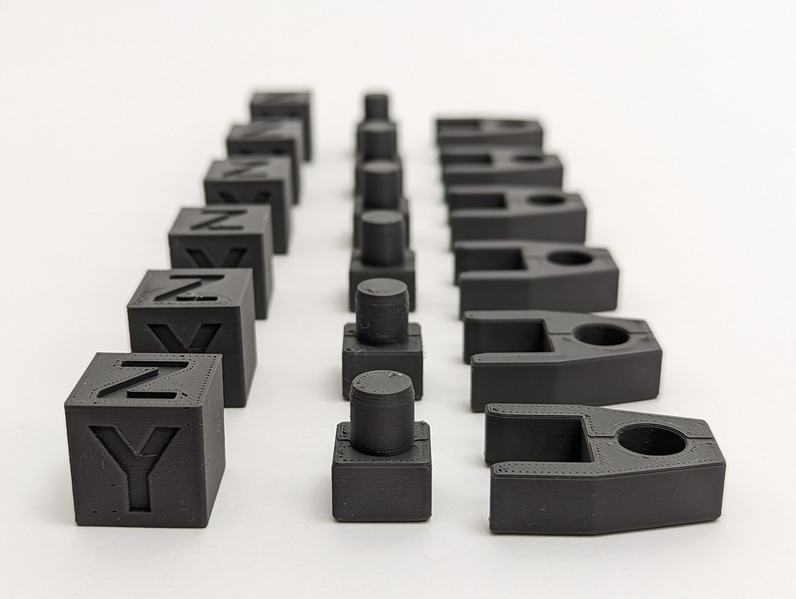
What could be better than a perfectly calibrated and optimized 3D printer? 😀
Learn how to increase the dimensional accuracy of your 3D printer step by step. Read how to check your 3D printer using the XYZ calibration cube and improve accuracy by optimizing the flow rate. At the moment I am still testing and designing my own test bodies to optimize the flow rate without calipers. All based on the article linked below, which is a very good starting point for optimization.
Thanks to the PrintFit System and the associated possibility of realizing gaps of different sizes between 3D printed parts, your 3D printer does not have to be calibrated to the tenth of a millimeter. But if your 3D print setup does not produce suitable 3D print connections even with the PrintFit system, it is time to take a closer look at your 3D printer.
The article contains affiliate links / advertising links, these are marked with an asterisk (*). If you make a purchase through these links, I may receive a commission at no additional cost to you.
Test 3D printer accuracy
The agony of choosing the right caliper
A caliper is a must, because the deviations in the tenths of a millimeter range are to be measured. Here, as always, the choice for the right one is not easy.
Either a:
- low-cost no-name analog vernier caliper (Amazon.com US)* or
- if it can be something better, then an analog caliper from Mitutoyo Mitutoyo vernier calipers (Amazon.com US)*
Analog calipers are only for those who are able to read nonius or want to learn the oldschool way and show off with it :).
Digital calipers are easier to read, also here from:
- low-cost digital caliper (Amazon.com US)* to
- professionel Mitutoyo digital caliper (Amazon.com US)*
Whether analogue or digital, the following applies: the more expensive, the more precise. So it is quite possible that the cheap caliper from the hardware store is off by +/- 0.2 mm and is therefore actually useless for the calibration of your 3D printer.
My personal experience with a cheap digital caliper from the hardware store:
As I used it, I noticed that the movable measuring arm wobbled so much that the measurement inaccuracy was definitely more than 0.2 mm. If you experienced such a behavior, it is possible to partially fix it. On the side where the locking screw sits, there are two very small screws that can be used to adjust the play of the moving part of the caliper. Tighten these so that the moving part can just about move and wobble as little as possible. After adjusting the tiny screws, the first problem was solved. However, I noticed that the small calipers were completely useless for measuring internal dimensions, since the values displayed are about 0.5 mm offset (measured through a comparison measurement with a more precise caliper).
So be careful, as always: “You buy cheap, you buy twice” and don’t put too much trust in cheap calipers.
A little tip: Before measuring, always wipe the measuring surfaces clean and check the zero point.
Printing a XYZ test cube
In any case, it is good to print a test cube. You can find them on every 3D printing platform to download.
Download the STL files and print the test cube with your usual filament and slicer settings.
When measuring the cubes, pay particular attention to whether an elephant’s foot is formed. This happens if the first layer is larger than the following ones. If so, then solve that problem first. Martin from the3dprinterbee.com has written a very good article on spotting and avoiding elephant foot mistakes.
If there is no elephant’s foot and the deviations in the cube dimensions are in the range of +/- 0.1 mm, the basic calibration of the printer is great and ok. However, if the deviations of the printed test cubes are far above the standard tolerance range (direction +/-0.3 mm), the settings in the firmware on the 3D printer may not be correct. The best thing to do here is to search the Web for your own 3D printer plus the keyword: calibration.
Thanks to the PrintFit System, all my projects supporting it should be easy to print and assemble with a 3D printer that prints within the standard manufacturing deviations (+/- 0.2 mm). If a connection is too tight or loose, simply print the next larger or smaller part, test and replace it.
Material flow optimization
If you want to further increase the printing accuracy, it is recommended to optimize the line width or the material flow. The material flow is also called flow rate or extrusion multiplier. There are optimization possibilities in the range of 0.2 mm.
However, each filament must be considered individually, and the settings found must be saved in the slicer. Stephan from drucktipps3d.de has made a very good tutorial for setting the material flow. Unfortunately only in German, maybe use the Google translate Extension for Chrome.
Based on his tutorial, I am currently developing and testing my own test specimens to offer step-by-step instructions for material flow optimization.
Do you have any other tips to increase the accuracy of 3D printers or found other good articles about it? Please let me know about your experience in the comments. See you soon, happy printing!


0 Comments