
A 3D printed depth caliper, also known as a depth gauge, should not be missing in any workshop. Super practical for measuring depths in difficult places, for easy positioning of, for example, brackets and much more.
Consisting of only two printed parts with an already integrated locking lever, the 3D print depth gauge can be printed completely and does not require any additional purchased parts.
Attention, the 3D print models of the depth caliper are included in the 3D print files of the DIY 3D printer enclosure.
The article contains affiliate links/advertising links, these are marked with an asterisk (*).
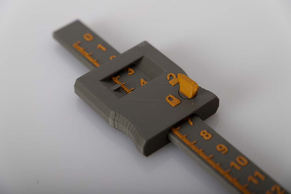
The 3D printed depth gauge is particularly beautiful when the numbers and symbols are printed in a different color. This is easy to set up in most conventional slicers and can mostly be programmed with a few simple commands.
The 3D printer pauses briefly at the relevant height in the Z direction to carry out a manual filament change. He then continues to print in the selected color and the symbols and numbers of the 3D print depth caliper are easier to distinguish.
Integrated locking mechanism in the locking block
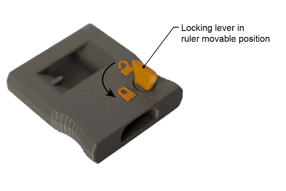
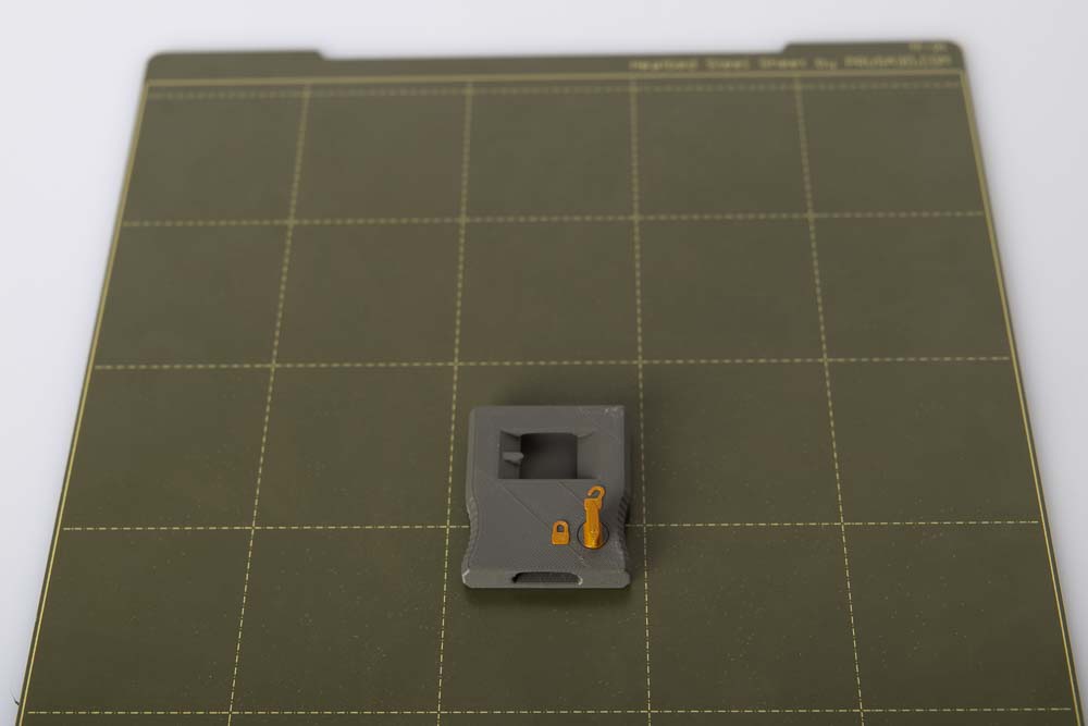
The locking lever and mechanism are already printed into the locking block. During the printing process, the locking block and the locking mechanism also grow, although these have no physical connection with one another. This allows the locking mechanism to rotate easily after detaching it from the build plate. However, its movement is limited upwards and downwards and thus remains in the locking block. With a kind of cam at the level of the ruler, it can block and release the ruler by turning it.
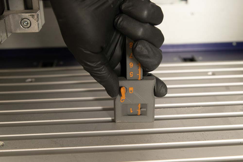
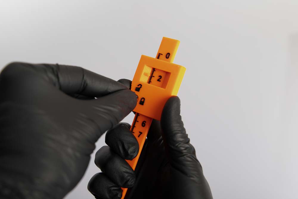
The “open lock” and “closed lock” symbols indicate the position of the lever.
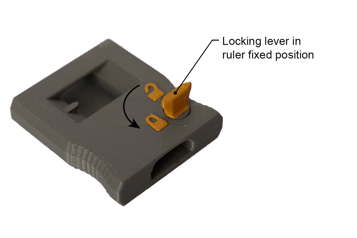
Here the locking lever is turned to the ruler fixed position. The opening in which the ruler later runs is now smaller and a ruler located in it would be fixed.
Areas of application for the 3D printed depth caliper
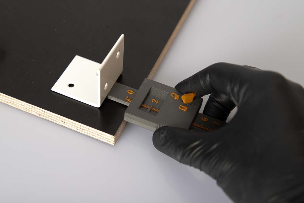
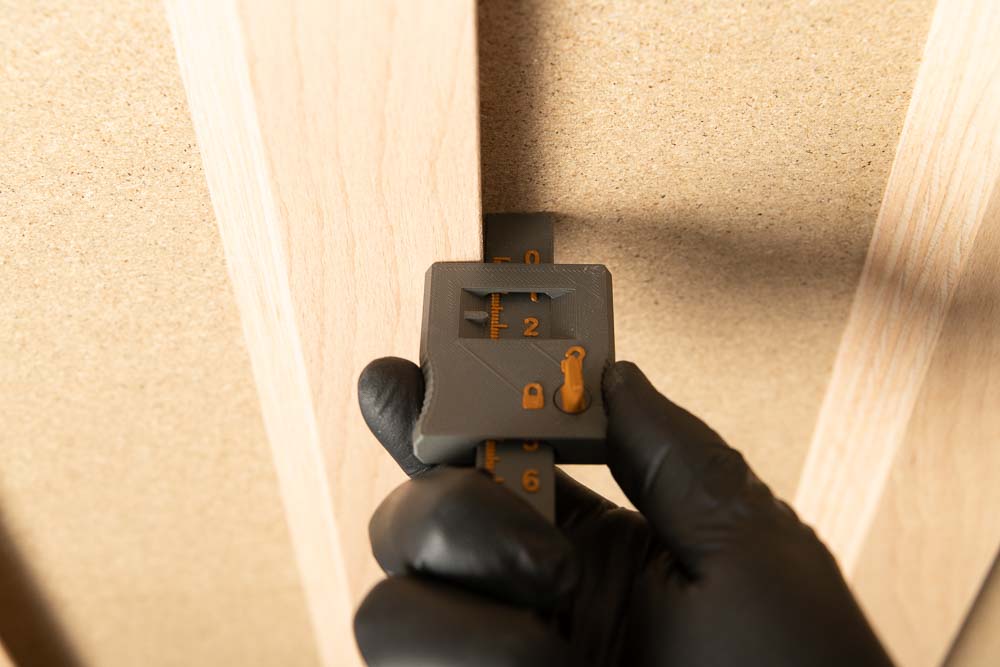
The 3D printed depth gauge works like a conventional depth gauge and is suitable for measuring depths and thicknesses, positioning brackets and much more.
Clear advantage, if the depth gauge is lost or broken, just start your 3D printer. Or an additional depth gauge is required for a project – no problem, start the 3D printer and after a short time it is ready.
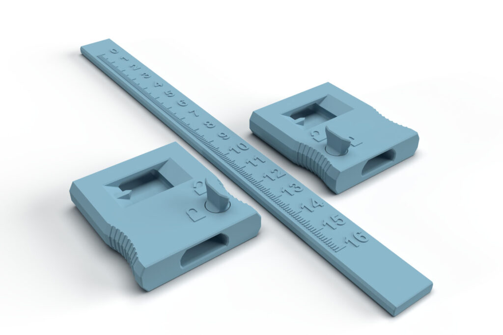
Right-handed and left-handed version in the 3D print files
Another advantage, the 3D print files contain two different versions. One is optimized for holding the ruler with the right hand and the other for the left hand. Which version you print is up to your personal preference.
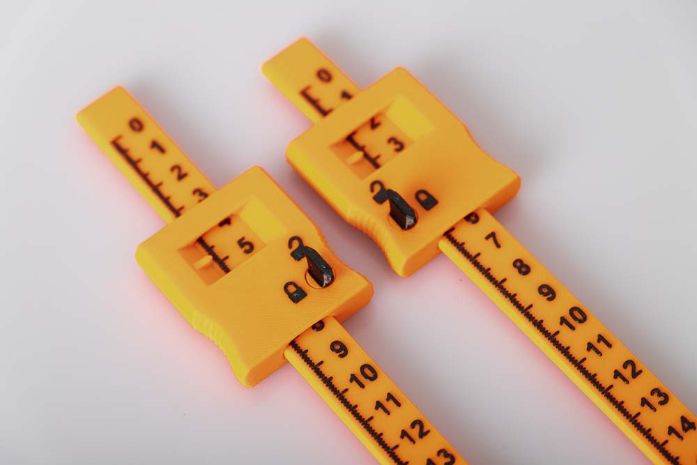
Left-handed and right-handed versions of the locking block. One has the locking lever on the left side of the block and the other has it on the right side. In this way, the ruler scale is not covered by the hand which is turing the lever.
The version with the lock on the left is suitable for holding the ruler and the block with the right hand and actuating the locking lever with the left hand.
The version with the lock on the right is suitable for holding the ruler and the block with the left hand and actuating the locking lever with the right hand.
3D Print Files
The files for the required 3D printed parts are available here in the shop.
These are digital products, you get all the files you need to print the parts yourself in a ZIP-folder. The STL-files for all the required components are included.
Attention, the 3D printed models of the depth gauge are included in the 3D print files of the DIY 3D printer enclosure.
- 005400_Ruler
- 005500_Lock_Left
- 005600_Lock_Right
The largest 3D printed part of this project (ruler) requires a base (X,Y) of 200 x 16 mm, the highest part (locking block) is 17 mm high (Z). By turning the ruler 45° diagonally, it only needs a print base of 160 x 160 mm. So any 3D printer with a build space (X, Y, Z) of at least 160 x 160 x 20 mm is suitable for this project.
3D print settings
For all components of the 3D printing depth caliper:
- Layer height 0.2 mm and 50% infill (rectangular)
The following settings have proven useful for the PETG filament used:
- Nozzle temperature: 250°C (First layer: 240°C)
- Bed temperature: 90°C (First layer: 85°C)
- Perimeter speed: 45 mm/s (First layer: 10 mm/s)
- External and short perimeter speed: 25 mm/s (First layer: 10 mm/s)
- Infill speed: 80 mm/s (First layer: 10 mm/s)
- Top solid infill speed: 40 mm/s
The following settings have proven themselves for the PLA filament used:
- Nozzle temperature: 215°C (First layer: 215°C)
- Bed temperature: 60°C (First layer: 60°C)
- Perimeter speed: 40 mm/s (First layer: 20 mm/s)
- External and short perimeter speed: 25 mm/s (First layer: 20 mm/s)
- Infill speed: 80 mm/s (First layer: 20 mm/s)
- Top solid infill speed: 40 mm/s
Used 3D printing filament and 3D printer
3D printer used: Prusa i3 MK3s* with a standard 0.4 mm nozzle
For the dark grey/gold version, 3D Jake ecoPLA Matt Dark Grey* and 3D Jake ecoPLA Matt Orange* were used.
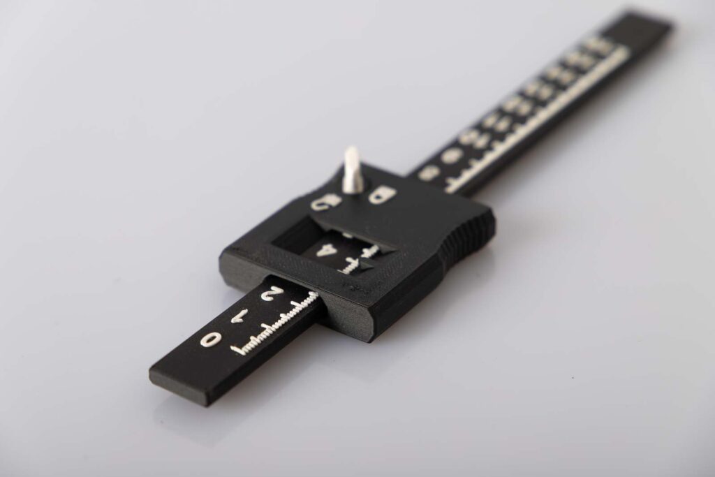
For the black/white version, 3D Jake ecoPLA Matt Black* and 3D Jake ecoPLA Matt White* were used.
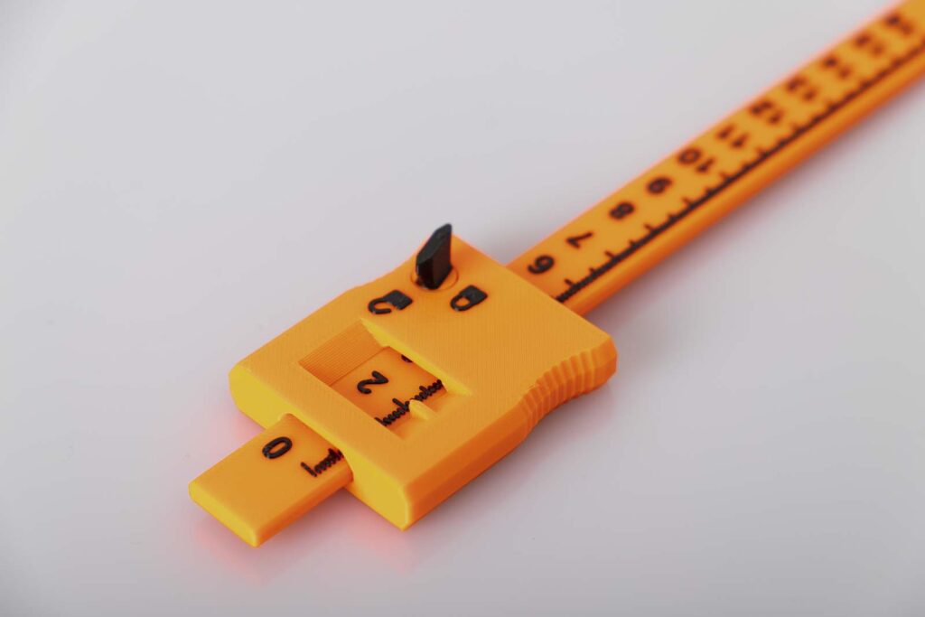
For the orange/black version, Prusament PETG Prusa Orange* and Prusament PETG Jet Black* filament were used.
With the selected settings, approx. 23 g of filament is printed for the 3D printed parts of the 3D printed depth gauge.
The PETG filament used (29.90 EUR/kg) is 0.70 EUR and the PLA filament (24.99 EUR/kg) is only 0.60 EUR filament material costs per 3D printing depth caliper.
The total 3D printing time for the two 3D printed components is approx. 2 hours.
Instructions: Build the 3D printed depth caliper
Assemble the DIY 3D printed depth caliper
The project is very simple, print out the required parts and insert the ruler in the block. If you want to print the parts in two colors, then at the end of this guide there is a link list to instructions which explain how two-color 3D printing works with the common slicers.
Required 3D printed parts
- 1 pc 005400_Ruler
Layer height 0.2 mm and 50% infill (rectangular)
A filament / color change was carried out here at a height of 4 mm.

After completion, leave the ruler on the heating bed or printing plate and let it cool down to room temperature. If you remove it while it is still warm, it could be warping while cooling down.
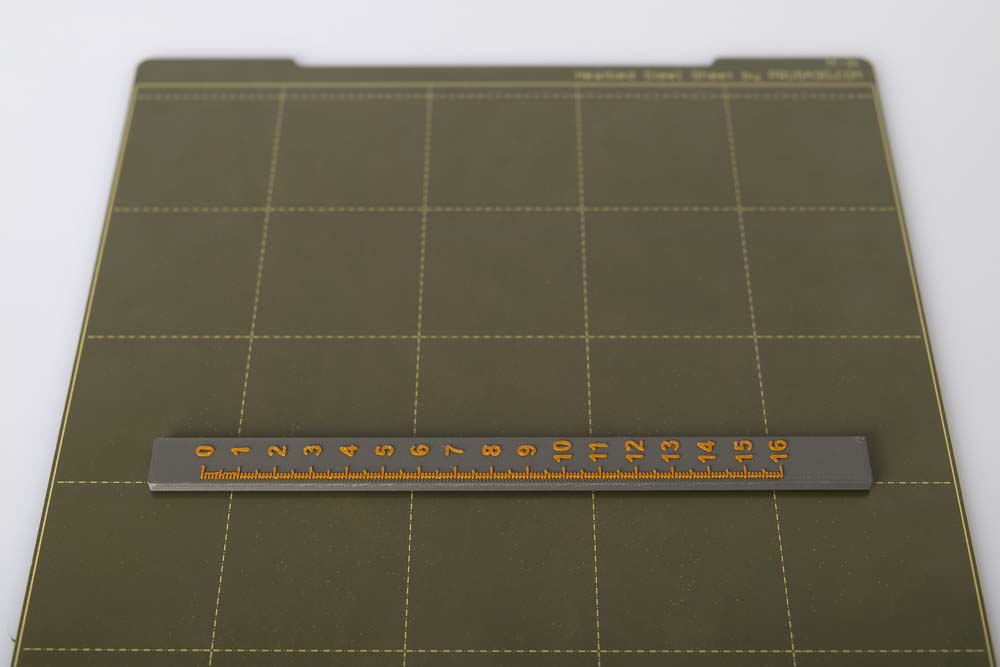
Before use, check the distances of the ruler scale of the 3D printing depth gauge with a standardized ruler. It could be that the 3D printer is not accurately calibrated. If there are deviations, the axes of the 3D printer must be recalibrated.
If the 3D printer is reduced to 50% printing speed just before the digits and the details, then the details are going to be printed sharper and better looking.
- 1 pc 005600_Lock_Right
or 1 pc 005500_Lock_Left depending on personal preference.
Layer height 0.2 mm and 50% infill (rectangular)
A filament / color change was carried out here at a height of 10 mm.
After detaching the locking block from the print plate, test whether the locking lever can be turned. It may take some force on the first turn to break any residual filament between the locking mechanism and the block. Please do not use excessive force here, it should only be necessary very little, if at all.
The assembly is very simple, print out the parts and put them together. Before inserting the ruler, turn the locking lever to the movable ruler position.
If the ruler is difficult to push at the beginning, then simply push it out and in a few times and it will fit in well. If it sticks and won’t move, check to see if the ruler needs deburring. If that doesn’t help either, scale the width of the ruler a little smaller in the slicer, but never scale the length of the ruler. Then print the ruler again, with the smaller dimensions.
Two-color printing with common 3D print slicers
If the 3D printed depth gauge is going to be printed in two colors, then the filament change must be set in the slicer. Following are the links to the instructions for this in the most popular slicer programs:
PrusaSlicer color change – super easy, here it is possible directly in the slicer with just a few clicks.
Cura Slicer color change – here is a step-by-step guide on how to activate the filament change script.
Simplify 3D Slicer color change – here is a short guide in connection with the Ender 3 v2 how to insert the required script.
OctoPrint Slicer color change – here are instructions for using the required scripts in OctoPrint.
In addition, close-up shots of the two-color 3D printed depth calipers:
Operating manual for the depth caliper
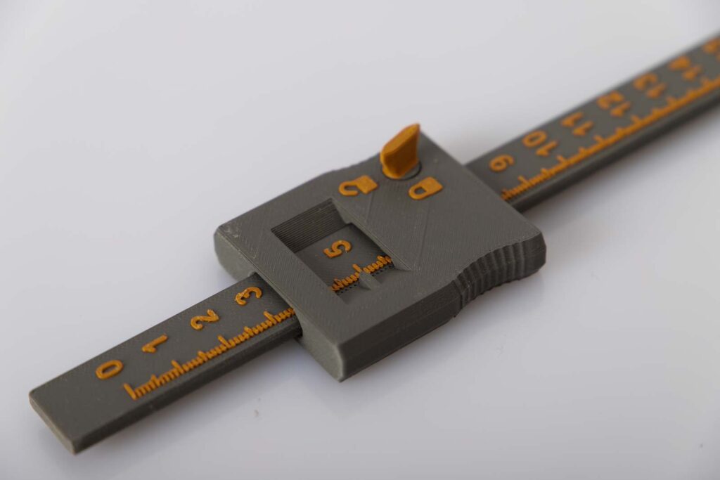
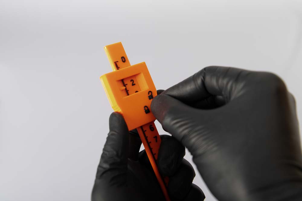
The depth caliper is intended for measuring depths, workpieces with steps and unreachable places. The length of the front face of the ruler to the surface of the locking block is the distance which is measured. The value that coincides with the highlighted peak in the measurement window of the locking block is the measured or set value.
The scale is divided into millimeter increments, each centimeter the respective value is written out. The accuracy of the depth caliper is related to how accurately the 3D printer is calibrated and how accurately the value is read. Before use, the scale of the ruler should definitely be checked with a standardized ruler.
The locking lever locks and unlocks the ruler by rotation. The closed lock symbol is the ruler fixed position, the open lock symbol is the ruler movable position.
Safety guidelines
Safety first! Read and follow the assembly instructions!
Read the entire instructions carefully and adhere to the instructions and safety guidelines. If anything is unclear, simply contact support (support@3d-druck-vorlagen.de). In the 3D print files for this project the instructions are also attached as PDF, keep it because you may need it later. A one-page quick guide is also included in the files with a link to this page – you will always find the latest version of the instructions here. If you are giving the project to someone else, then print out the instructions and, above all, the safety instructions and pass them on with the project.
Warnings and symbols


Safety instructions for this 3D printing project
Attention for all self-printed parts: Due to incorrectly set printing parameters, poor material, incorrect material selection, poor layer adhesion and other reasons, these can sometimes not meet the requirements needed on them and thus break, fail or their functionality cannot be guaranteed. In the event of a break, the parts can splinter and the fracture surface leave sharp edges. Take particular care when replacing these parts, there is a risk of cuts! Check 3D printed parts for cracks, stability and functionality at regular intervals and before using the project. If a part is damaged or unsuitable, do not continue to use the project until the broken part has been replaced with a new, improved part.
When printing parts, sharp edges can occur (usually on the first layer), there is a risk of cuts! These edges have to be ground down in order to deburr them.
Disclaimer
The instructions and the associated files are an inspiration of Ingenieurbüro Dr. Janko GmbH to build this project yourself. Since Ingenieurbüro Dr. Janko GmbH has no way of checking and influencing the required quality of the printed components and purchased parts as well as the quality of the assembly and the correct functioning of the project or if any inadmissible changes and modifications to the project has been made, Ingenieurbüro Dr. Janko GmbH accepts no liability for functionality, stability or damage incurred by the project.
0 Comments