
The singing and rattling of your 3D printer is driving you crazy or is already calling the neighbors into action? Decouple your 3D printer from the ground with a damper board and reduce the printing noise!
The article contains affiliate links / advertising links, these are marked with an asterisk (*). If you make a purchase through these links, I may receive a commission at no additional cost to you.
Why build a damper board for 3D printer?
It’s simple: just to reduce the noise of the 3D printer. It prevents that the vibrations of the 3D printer are being amplified by a resonator. The table or shelf on which the 3D printer is placed is enough as a resonance body, which then amplifies the stepper motor noise many times over.
For my first 3D printer over 10 years ago, I screwed a wooden board directly to the wall in front of my desk. So, the printer’s vibrations were transmitted directly into the wooden panel and from there into the wall, the whirring, rattling, and singing of the stepper motors could be heard in every room of the apartment. The neighbors probably also thought that the world is going to end, but fortunately they couldn’t identify the source of the noises.
What happened? The vibrations of the 3D printer caused the shelf and the wall to vibrate. The wooden board and the wall in turn made the air vibrate, and so the adjoining rooms became resonators that amplified the vibrations even further.
You can think of the whole thing like a guitar: If only a string vibrates without being coupled to the guitar body, it is almost inaudible. If the string is coupled to the body, it causes the body to vibrate, and the volume of the string is multiplied.
Unfortunately, what is wanted with the guitar is unpleasant with the 3D printer.
Reduce the vibrations of the 3D printer and thereby reduce noise
The solution: A damper is needed to isolate the vibrations of the 3D printer and decouple it from the ground.
The most obvious idea was to put foam under the 3D printer, which brought a lot in terms of noise, unfortunately the printer rocked a lot due to the extremely soft bearing. This was neither good for the printer nor for the printed parts. The next experiments were made with a rubber anti-vibration mat for washing machines. These in turn were too hard and did not dampen well enough.
That’s why I started to print my own damper feet with flexible filament. These have the advantage that their flexibility can be adjusted very well by varying the design and the density (infill and number of perimeters). It is important to print the damper feet not too tight and not too soft.
Conclusion: Basically, the softer the dampers, the better the vibration isolation. This result in less noise when printing. At the same time, however, the swinging and the rocking of the 3D printer increase.
What can be done to prevent the 3D printer from swinging too much? The solution lies in an additional weight on the 3D printer. The easiest way to do that is with a damper board to which additional weights are attached.
Why is an additional weight on the damper board an advantage?
An effect that is also used in large production machines also helps with home 3D printers. If an additional mass is coupled to the vibration generator, this reduces the maximum oscillation amplitude and shifts the resonance frequencies.
In the case of large machines, it is realized by bolting it to a machine foundation, which reduces the vibration amplitudes compared to machines without a foundation. To prevent the entire hall from vibrating, the machine foundation is then vibration-insulated, i.e., decoupled from the rest of the hall foundation with rubber or special dampers.
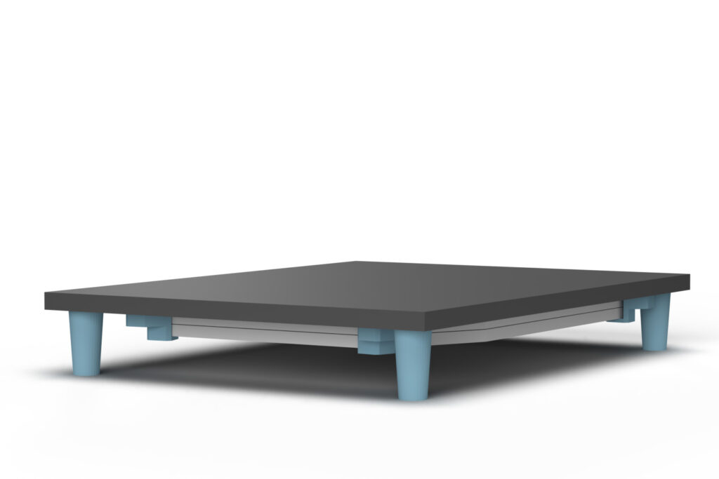
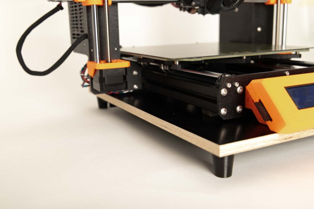
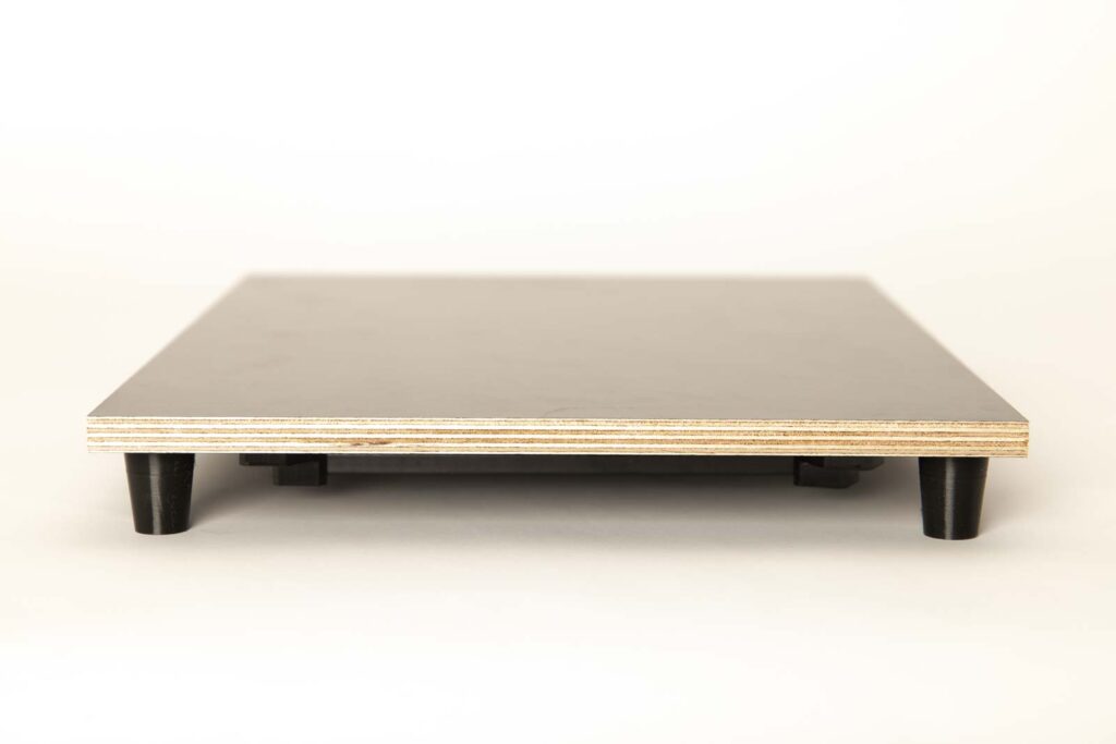
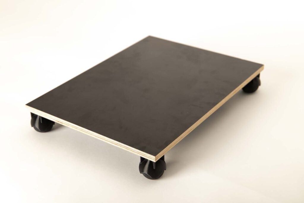
Adding weight to the 3D printer does the same thing. The 3D printer is placed on a board that is equipped with additional weights and the board is then decoupled from the ground using damper feet.
On the one hand, this reduces the vibrations in the subsurface (table, enclosure, or shelf), which reduces the printing noise. At the same time the mass of the 3D printer is increased to prevent that it is swinging too much.
DIY 3D printer damper – build it yourself with or without flexible filament
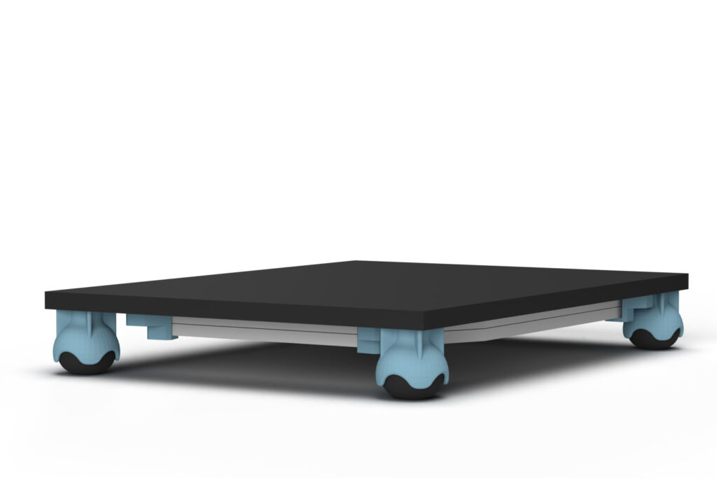
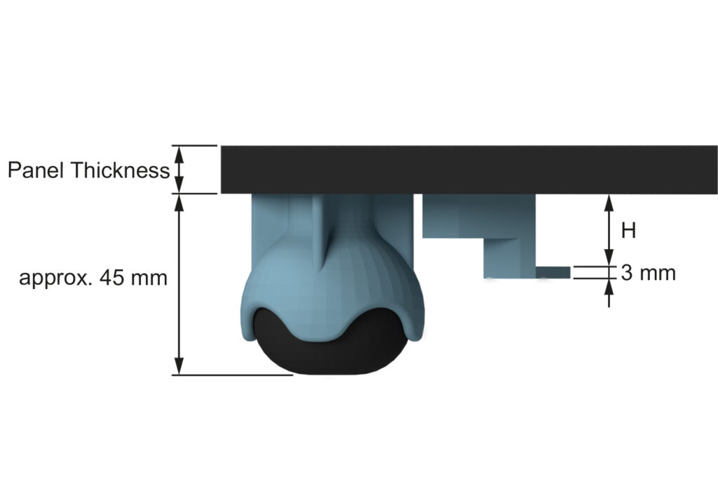
Flex filament (TPE, TPU, etc.) is one of the more demanding 3D printing materials and usually requires a direct drive extruder. You don’t want to get into it or do you have a Bowden extruder on your 3D printer, that’s no problem. To be able to build a damper board without flexible filament, there is a simple trick: instead of using Flex filament for the damper feet, you can also use squash balls.
With squash balls, the aim is to dampen any impact as good as possible to avoid going too fast. It may sound paradoxical, but when it comes to squash, the pros play with balls that hardly bounce at all and absorb a lot of the energy, making them ideal for your damper board. Instead of the damper feet made of flexible TPE or TPU filament, mounts for squash balls made of classic filament are printed.
For the Flex filament used, I will give you a few more tips in the 3D print settings to get clean and beautiful 3D printed flexible parts.
Choose different weights with the included weight holders
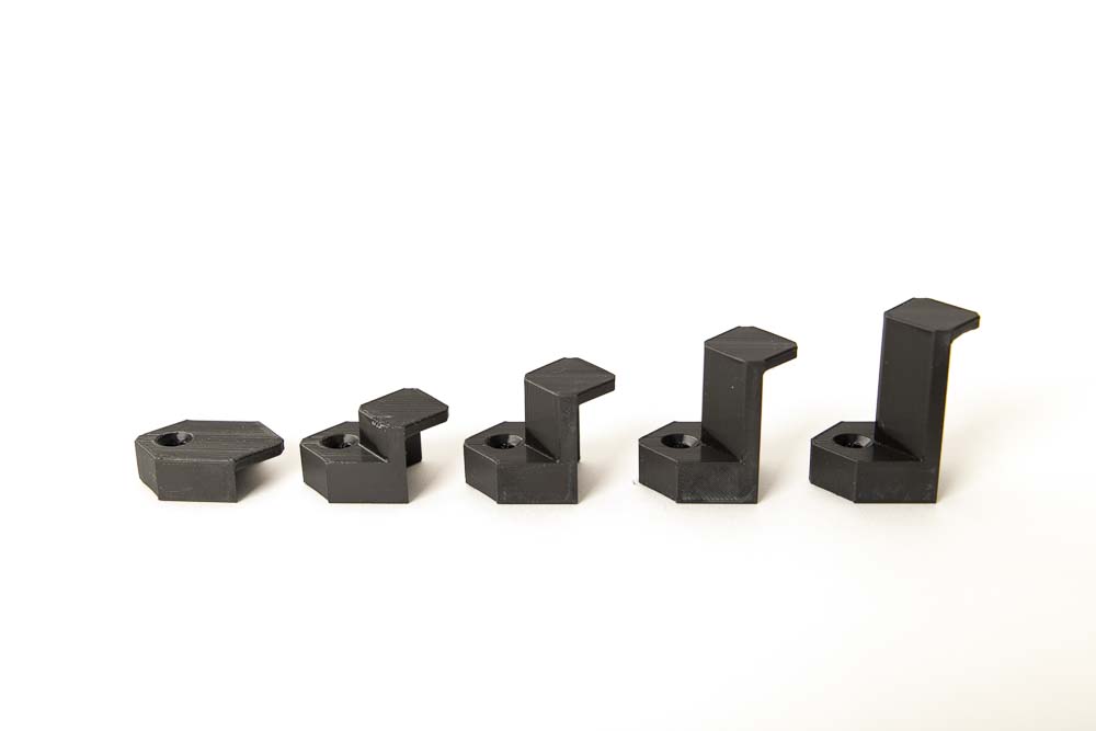
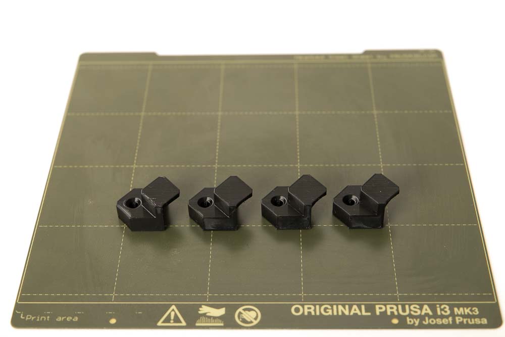
The project’s 3D print files contain 33 weight brackets of different heights. Weights with thicknesses of 8 to 40 mm (in 1 mm steps) can be used.
Shown in the photo are the brackets with the heights: 8, 17, 25, 33 and 40 mm
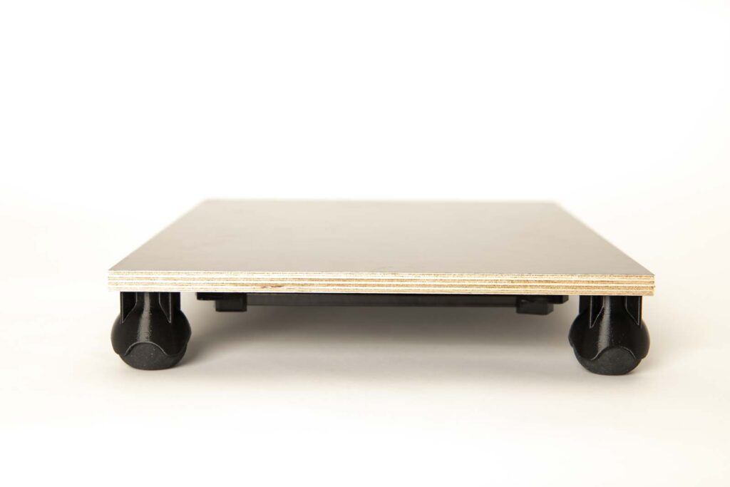
Damper board height overview
To be able to accommodate thicker weights and to adjust the dampening effect, four damper feet models of different heights are included in the 3D printed models.
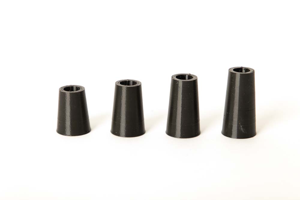
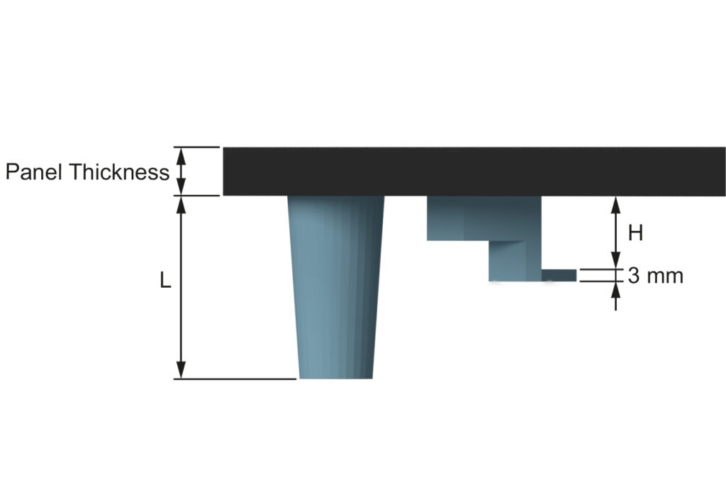
The STL files with damper feet in the lengths L= 30, 35, 40, 45 mm are included in the 3D printing templates.
An important factor for planning is how much space is available and how high the entire substructure can be. With higher damper feet, a good damping effect can be achieved even with relatively stiff flexible filaments, or thicker weights can be attached.
The rendered sketches with dimensions give a quick overview of the height of the damper board in its different versions.
3D print parts
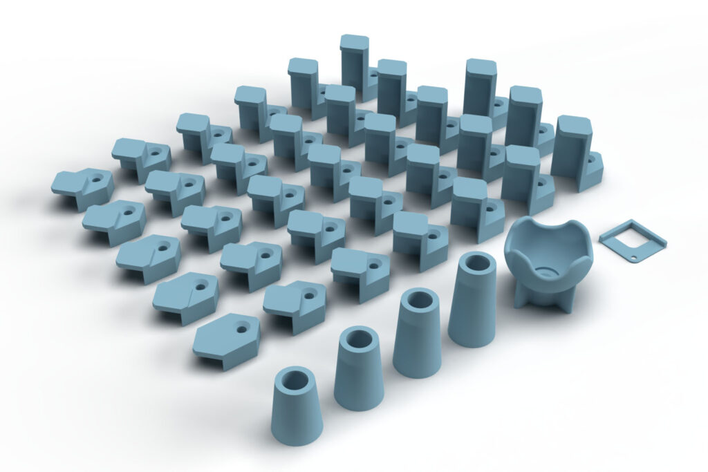
These are purely digital products, you get all the files you need to print the parts yourself in a ZIP folder. It contains the STL files for all required components and variants, additional accessories, as well as templates and installation aids. A total of 39 different 3D print models are included.
- 005700_Flex_Damper_Foot_L##
4 models with lengths L= 30, 35, 40, 45 mm - 005800_Weight_Bracket_H##
33 models for different weights with a height of H= 8 to 40 mm in 1 mm increments - 005900_Squash_Ball_Mount
- 006000_Stencil_Damper
The largest 3D printed part of this project (005900_Squash_Ball_Mount) requires a footprint (X, Y) of 46 x 46 mm, the highest part (005700_Flex_Damper_Foot_L45) is 45 mm high (Z). Any 3D printer with a build space (X, Y, Z) of at least 50 x 50 x 50 mm is suitable for this project.
3D print settings
For all the parts not printed with Flex filament:
- Layer height 0.2 mm and 100% infill (rectangular)
The following settings have proven useful for the PETG Filament* which was used.
- Nozzle temperature: 250°C (First layer: 240°C)
- Bed temperature: 90°C (First layer: 85°C)
- Perimeter speed: 45 mm/s (First layer: 10 mm/s)
- External and short perimeter speed: 25 mm/s (First layer: 10 mm/s)
- Infill speed: 80 mm/s (First layer: 10 mm/s)
- Top solid infill speed: 40 mm/s
For the 3D print part 005700_Flex_Damper_Foot_L## printed with flexible filament:
- Layer height 0.2 mm, 15% infill (rectangular) and 2 perimeters
Depending on the flexibility of your Flex filament, the damper feet can be printed even softer or harder using less or more infill and number of perimeters. Make sure that your feet don’t get too soft to be able to carry the 3D printer and the additional weights.
Tips for 3D printing flexible filament
Three more tips for printing with flexible (TPE, or TPU) filament:
- Print very slowly
- Very little preload on the extruder gears
- If the flexible filament sticks too much to the print bed – use Kapton (Polyimide) tape
Print very slowly – at only 25 mm/s
The flexible filament simply needs a more time to process, so turn the print speed all the way down.
The following settings have proven themselves for the Flex filament Fiberlogy Fiberflex 30D Black* used.
- Nozzle temperature: 240°C (First layer: 240°C)
- Bed temperature: 40°C (First layer: 40°C)
- Perimeter speed: 25 mm/s (First layer: 15 mm/s)
- External and short perimeter speed: 25 mm/s (First layer: 15 mm/s)
- Infill speed: 25 mm/s (First layer: 15 mm/s)
- Top solid infill speed: 25 mm/s
Why only little preload on the extruder gears?
To be able to process the flexible filament with the 3D printer, the preload on the extruder gears must be reduced. If the pressure of the gears on the flexible filament is too great, it wraps itself around the gears.
At first glance, that sounds paradoxical, better printing with very little pressure on the filament?
But since the flexible filament can be conveyed very well with the gears anyway due to its flexibility and stickiness, the problem with this material is the adhesion to the gear. As a result, it can happen that the flexible filament wraps itself around the gears and the printing process must be stopped as a result.
With the Prusa i3 MK3S, I unscrew the M3 cylinder head screw, which is responsible for the preload, until the entire screw head is visible.
What to do if Flex filament sticks very strong on the print plate?
The Fiberlogy flexible filament used here, sticks extremely strong to the PEI-coated print bed, so here is a tip for easy detachment: to avoid the flex material sticking to the print plate, simply stick a strip of Kapton (Polyimid) tape (Amazon.com US)* on the build plate before printing.
Of course, only where the printed parts should arise later. Since the area to be printed is now closer to the nozzle due to the tape, increase the first layer in the slicer to 0.4 mm. For more useful tips and help see also the article: The best 3D printing tools and accessories
Used 3D printing filament and 3D printer
3D printer used: Prusa i3 MK3S* with a standard 0.4 mm nozzle
3D printing filament used: In this guide Prusament PETG Jet Black* was used for all solid parts and Fiberlogy Fiberflex 30D Black* for the flexible damper feet.
With the selected settings, approx. 35 g PETG filament and 23 g FLEX filament are printed for the 3D printed parts of the damper board.
With the PETG filament used (29.90 EUR/kg) and the FLEX filament used (47.05 EUR/kg), the filament material costs are approx. 2 EUR per damper board (with flex damper feet and weight holder with a height of 17 mm).
The total printing time for all required components is approx. 7 hours. To calculate the total printing time, all printing times are added together, with the entire quantity of a 3D printed component being printed at once.
A PETG filament is recommended because of the higher stability and lower distortion. The parts can also be printed with ABS or ASA, but these place higher demands on the 3D printer and the operator. The widely used PLA is not recommended, because technically more demanding parts are not stable enough due to the more brittle nature of this material and the lower layer adhesion.
Bill of materials: Needed purchased parts to build the damper board
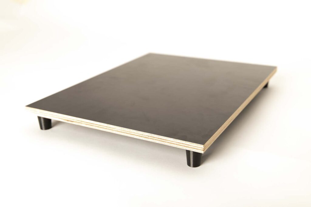
- 1 pc Plywood board 12″x16″ (400×300 mm) thickness = 1/2″ (12 mm) black (Amazon.com US)* (approx. 14 USD / pc) – pay attention to the space requirements of the 3D printer and the additional weights when choosing the board dimensions (the linked plywood need to be cutted to size)
- 8 pcs Wood screws #7 x 3/4″ (approx. 4×20 mm) flat head (Amazon.com US)* (approx. 9 USD / 100 pcs)
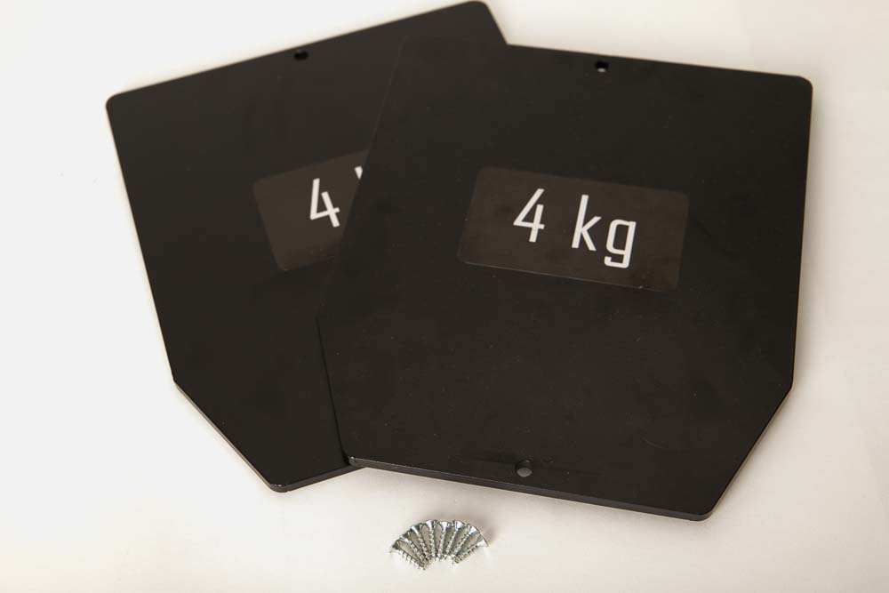
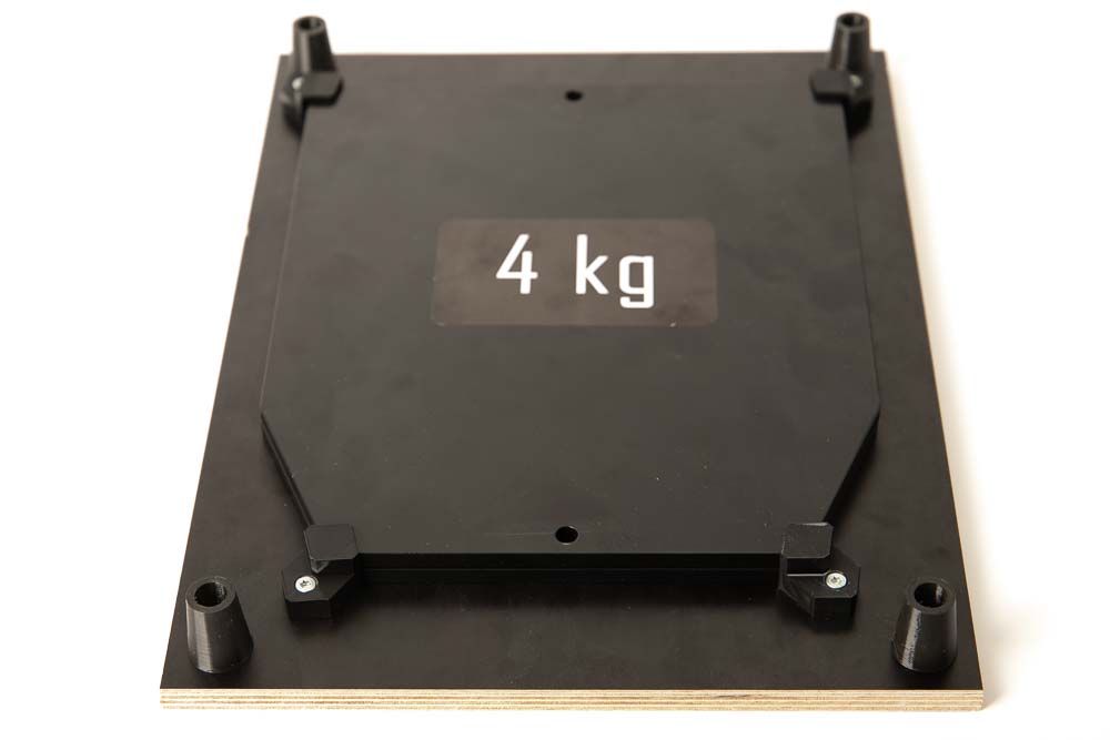
- 2 pcs Steel plates – weight for weight jacket 8.8 lbs (4 kg) (Amazon.com US)* (approx. 61 USD / 2 pcs) – other weights can also be used
The total cost of the purchased parts comes to around 76 USD if the plywood is ordered directly from amazon.com and if only the costs for the parts required for a damper board are added up.
If the weights, which make up most of the costs, are not purchased – because there are still a few old dumbbell weights lying around in the basement, the costs for the purchased parts can be reduced to around 15 USD.
Optional, if you want to use squash balls for the dampers instead of flexible filament:
- 4 pcs Squash balls – Double yellow dot (Amazon.com US)* (approx. 20 USD / 4 pcs)
Alternative purchased parts
Screws are usually much cheaper in the hardware store and, above all, can be bought in exactly the required quantity.
The wooden plywood board is also cheaper directly from auprotec.com, or you can simply have it cut to size at a hardware store. The panel thickness should not be less than 1/2″ (12 mm), the brackets and feet are designed in such a way that the #7 x 3/4″ (4×20 mm) wood screws used penetrate a maximum of 10 mm deep into the panel. Thinner plates are also not stable enough for the 3D printer and the weights.
For planning the panel dimensions, consider the space required by your 3D printer and the additional weights to be attached. The 12″ x 16″ (300 x 400 mm) board fits very well for the additional weights used and offers enough space for a Prusa i3 MK3S or a Prusa MINI.
Instead of the linked steel plates, various other weights can be used, from weight plates to simple steel plates or even thin stone plates. In the 3D print files are many different weight bracket models with different heights. Simply measure the thickness of the weight and select the weight bracket STL file with the next largest height.
Required tools
As always, a new project is the best excuse to buy new tools ;), not all are required but some help save some time.
- Cordless drill (Amazon.com US)*
- Screwdriver bit set (Amazon.com US)*
- Sandpaper 240 Grit (Amazon.com US)*
- Screwdriver set (Amazon.com US)*
- Wood drill bit 2 mm (Amazon.com US)*
- Marker pen (Amazon.com US)*
Assembly instructions: Build a DIY damper board for your 3D printer
The step-by-step instructions follow to build the damper board for the 3D printer yourself, please read and observe the safety guidelines for assembly.
Safety Guidelines
Safety first! Read and follow the assembly instructions and the operating manual!
Read the entire assembly instructions and operating manual carefully and follow the instructions and safety warnings. If anything is unclear, simply contact support (support@3d-druck-vorlagen.de).
These instructions are only intended for persons of legal age (over 18 years old). If you lack knowledge in handling the tools or processes that occur, then it is essential to seek the help of trained persons. The preparation and assembly of the project is at your own risk.
Legend: Warnings and Symbols


General safety instructions for assembling the project
Wear protective goggles to protect your eyes during all processing steps that can produce chips (sawing, drilling).
Wear assembly gloves to protect your hands during all processing steps in which saws or knives are used. Do not wear gloves when drilling, there is a risk of being drawn into the drill.
When printing parts, sharp edges can occur (usually on the first layer), there is a risk of cuts. These edges must be deburred.
Step 1: Preparing the Plywood Panel
To make it easier to assemble the feet and weight brackets later, it is best to drill all the necessary pilot holes right away.
Required 3D printed parts
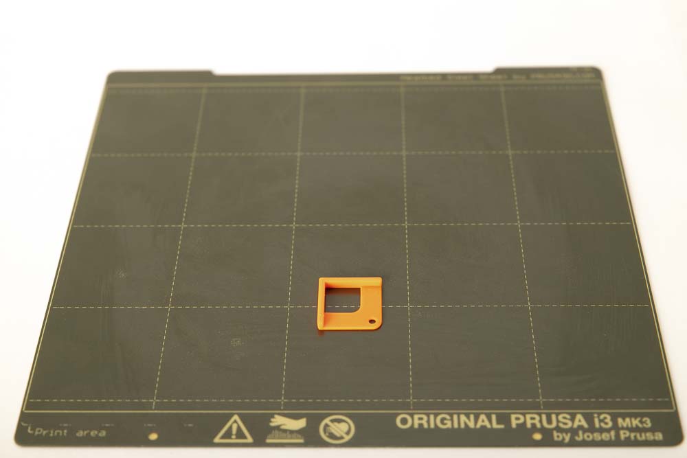
- 1 pc 006000_Stencil_Damper
Layer height 0.2 mm and 100% infill (rectangular)
- 4 pcs 005800_Weight_Bracket_H##
Choose the right weight bracket for your weights here. To do this, measure the thickness of your weights and use the next larger bracket. The height of the weight bracket corresponds to the weight height to be held. The total height of the bracket is calculated by adding additional 3 mm.
Height H= 8 to 40 mm in 1 mm increments
For the steel plates used in these instructions (4 kg ordered at Amazon.de), weight brackets with a height of 17 mm are used here. For the 8.8 lbs ordered from Amazon.com please check the height an choose the right weight brackets.
Layer height 0.2 mm and 100% infill (rectangular)
Be sure to print the brackets with 100% infill and a mechanically robust filament (e.g.: PETG, ABS, ASA).
Preparation of the wooden panel
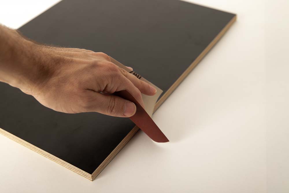
If the edges of the panels are sharp, simply sand them off a little with fine sandpaper to deburr them.
Examine the panel and decide which side should show upwards later (the one with the more beautiful surfaces and edges).
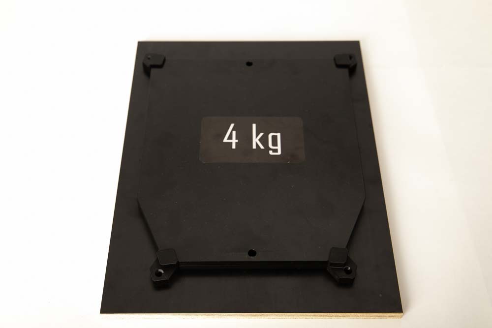
The pilot holes for the feet are set on the underside of the plate. It is not important whether the flexible damper feet or the squash ball holder are attached later. Always measure 20 mm from both edges. If you have printed out the stencil, it’s super simple.
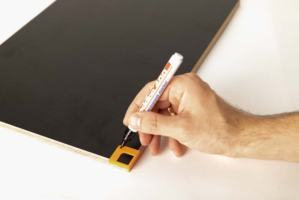
Position the stencil in the corners and mark the pilot hole through the hole of the stencil.
A marker pen or a wood screw can be used here.
Then place the intended additional weights on the underside. Make sure that they are not too close to the damper feet or squash ball mounts, so that they can be screwed on later without any problems.
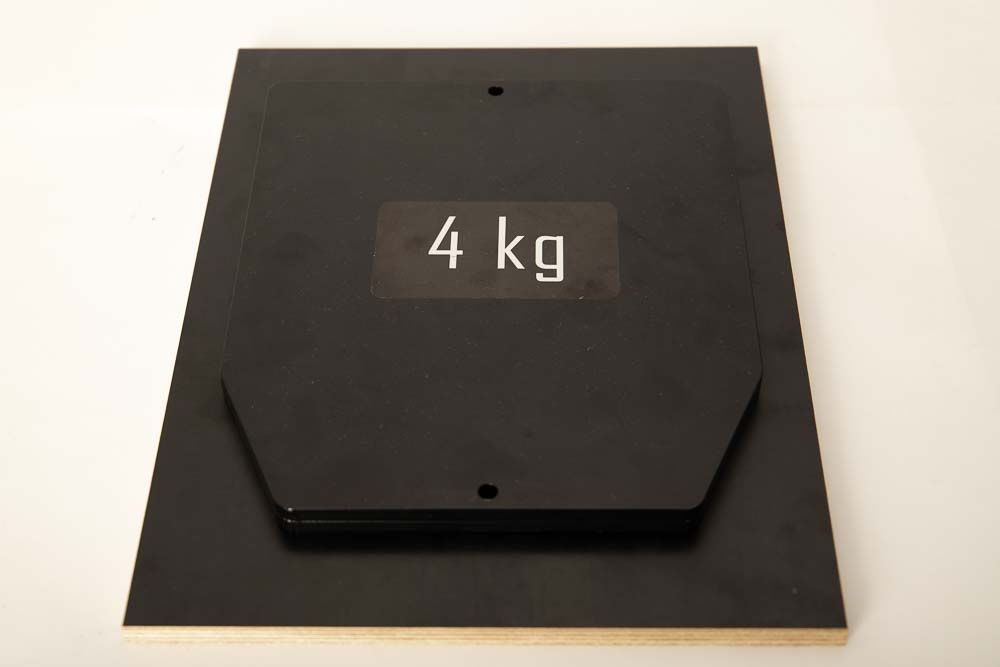
Place the selected weights as centrally as possible to distribute the additional mass evenly over the damper feet.
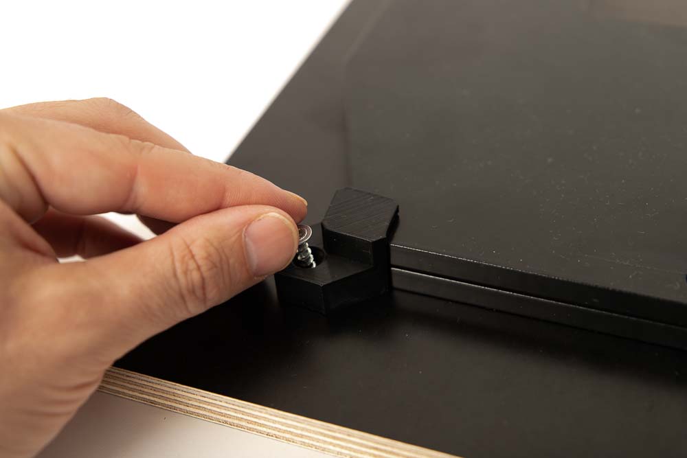
Place the weight brackets on the weights and use a wood screw to mark the pre-drilling point through the hole of the brackets.
Repeat this for the chosen number of weight brackets, in this case 4 pieces are enough to fix the steel plates.
When all markings have been made, remove the stencil and the weights.
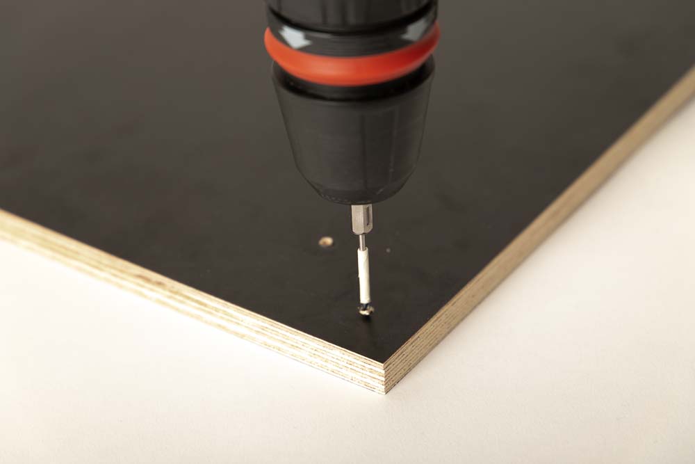
Pre-drill about 9 mm deep at all 8 markings with a 2 mm wood drill bit, be careful not to drill through the wooden board.
Tip: To do this, cover the wood drill bit with adhesive tape at 9 mm depth (for the selected 1/2″ (12 mm) wood board).
The board is now ready for mounting the shock feet and weights.
Step 2: Attach 3D printed brackets and damper feet
In this step, the flexible filament damper feet or the squash ball mounts, and the weights are attached on the damper board.
Required purchased parts
- 8 pcs Wood screws with flat (countersunk) head
- 2 pcs Steel plates – weight for weight jacket 4 kg (8.8 lbs)
Alternatively, use other weights that can be easily attached to the wooden board using the weight brackets.
For the variant without Flex filament:
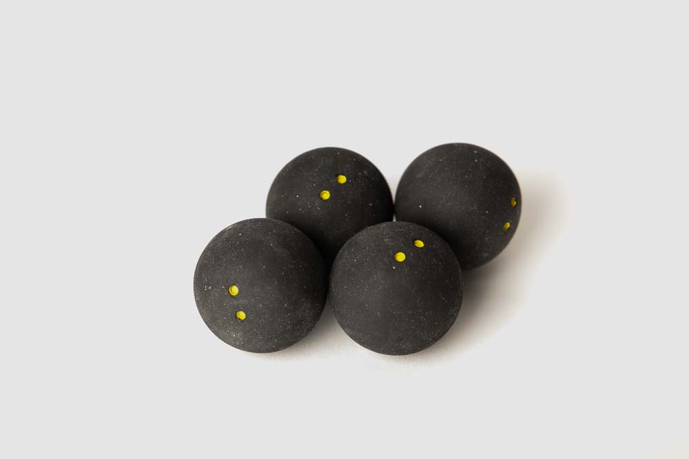
- 4 pcs Squash balls – Double yellow dot
Required 3D printed parts
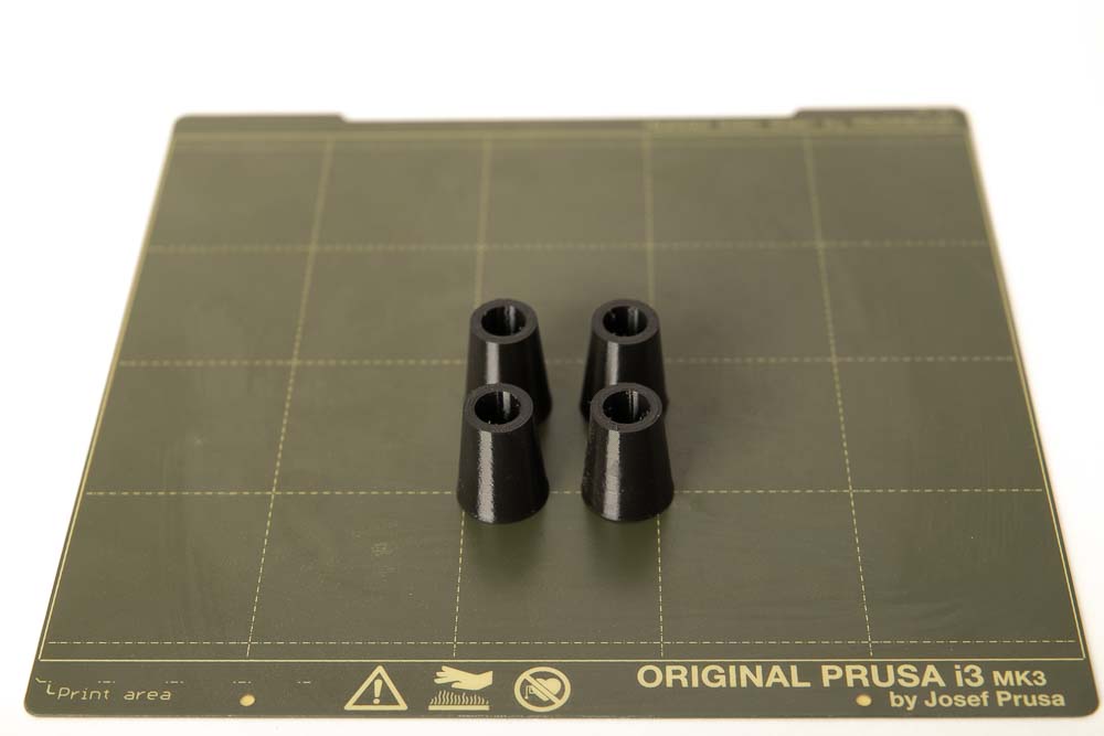
- 4 pcs 005700_Flex_Damper_Foot_L##
STL files with the lengths L= 30, 35, 40 and 45 mm are available. On the one hand, the choice depends on how much space is available and how high the chosen weights are. On the other hand, how strong the damping effect should be.
With the Fiberlogy Flex filament used, the damper feet were printed with a height of 30 mm and the following settings were used: layer height 0.2 mm, 15% infill (rectangular) and 2 perimeters.
The infill and the number of perimeters depends on the flexibility of the flexible (TPE or TPU) filament used and on the total weight of the 3D printer and the additional weights. The basic rule is: as flexible as possible, but enough to stably support the total weight.
It is essential to check the flexible damper feet before start-up. Execute a test print to check whether they are mechanically stable enough. If not, print them with more infill and/or perimeters.
For the variant without Flex filament:
If you want to avoid printing with flexible filament, the squash ball mount is printed with PETG or another mechanical robust filament. The squash balls then later provide the necessary damping effect, which is why no flexible filament is required in this variant.
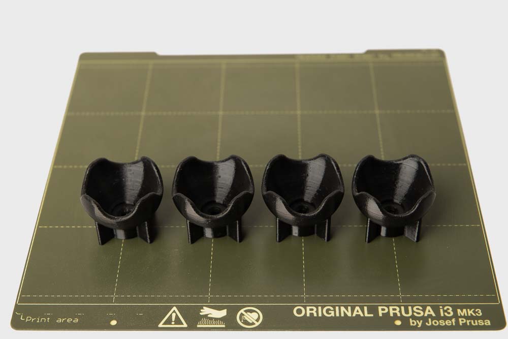
- 4 pcs 005900_Squash_Ball_Mount
Layer height 0.2 mm and 100% infill (rectangular)
Be sure to print the mounts with 100% infill and a mechanically robust filament (e.g.: PETG, ABS, ASA).
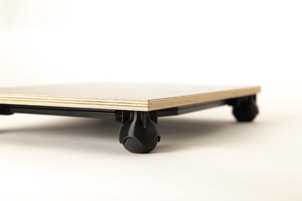
Installation of the damper feet
The four damper feet are fixed with the 20×4 mm (#7 x 3/4″) wood screws.
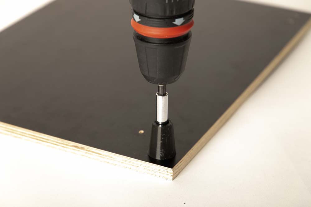
Put the wood screws through the hole in the damper foot and screw them into the outer pilot holes of the wooden board.
It is important not to over-tighten the screws. Depending on the flexibility of the damper foot, it will be squeezed too much, and the screw will protrude out of the top of the wooden panel. It is best to work step by step, tighten the screw a little, then test if the damper foot is fixed well enough. If not, then repeat until the damper is securely bolted to the plate.
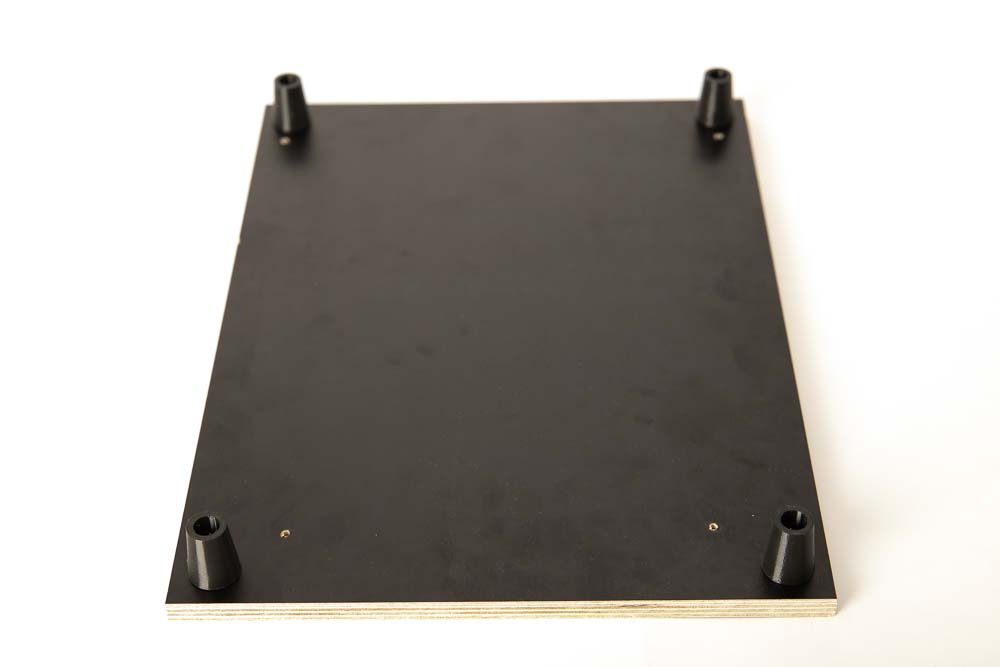
Perform this for all four damper feet.
Assembly of the squash ball mounts and the squash balls as damper feet
For the variant with the squash balls as a damper, the mounts are installed instead of the flexible damper feet.
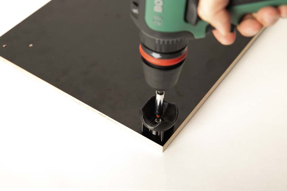
If the squash ball mounts are used, then screw the squash ball holders to the plate with the 4×20 mm (#7 x 3/4″) wood screws. Aligning the support bars at a 45° angle to the wooden board edges.
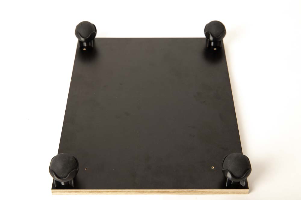
Perform for all 4 mounts. Then insert the squash balls into the mounts. The balls are going to stay there even is the board is flipped afterwards, because of the mount’s design.
Mounting of the vibration reducing weights
Then the weights are put on the wooden panel and the weight brackets are positioned.

Insert the 4×20 mm ( #7 x 3/4″) wood screws through the holes in the weight brackets and then screw them into the pilot holes you drilled in Step 1.
After fixing the last weight bracket, check if the weights are held securely.
Check if the weights are held securely and cannot fall out of the brackets.
If the weights are not held securely, screw them to the wooden board with additional weight brackets or use other weights.
The damper board is now ready for the first test. In the next step, the 3D printer is positioned, and the setup is thoroughly tested.
Step 3: Position and test the 3D printer
Finally, the 3D printer is placed on your damper board and a few test prints are performed to check whether everything is working properly.
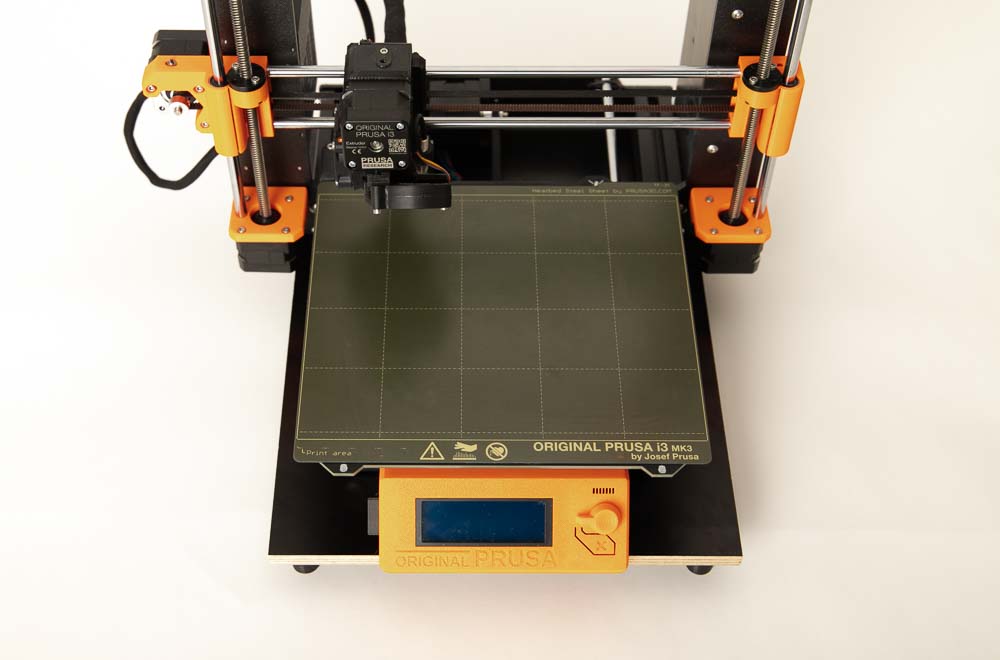
Place the 3D printer in the middle of the damper board.
Then check the weight brackets and damper feet.
Carry out the following checks before start the 3D print process / operation:
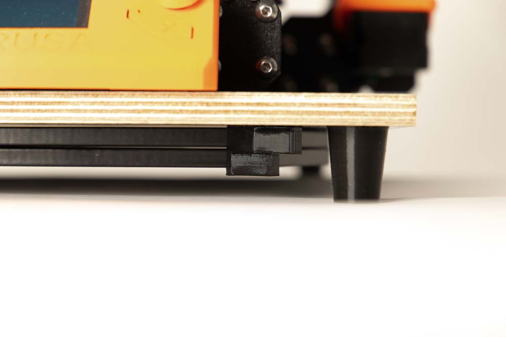
- Is there enough space between the weight brackets and the ground?
- When the damper board vibrates, how do the damper feet react – are they stable enough?
If the damper feet buckle or deform too much, do not use the damper board, but print the feet again with more infill and/or more perimeters.
Congratulations you can start the first test prints and enjoy the reduced background noise 🙂
Always pay attention to whether the 3D printer slips or shifts on the damper board during printing. If this is the case, then fix the 3D printer on the damper board, for example with double-sided adhesive tape.
Also pay attention to how the damper feet behave, do they deform too much or are they too stiff and transmit too many vibrations? Depending on this, they can be adjusted by variating the infill and/or the number of perimeters to be more rigid or more flexible.
Were all checks successful? Congratulations on building your DIY damper board!
Before final operation, be sure to read and follow the operating manual of the DIY anti vibration damper board and the safety instructions given there!
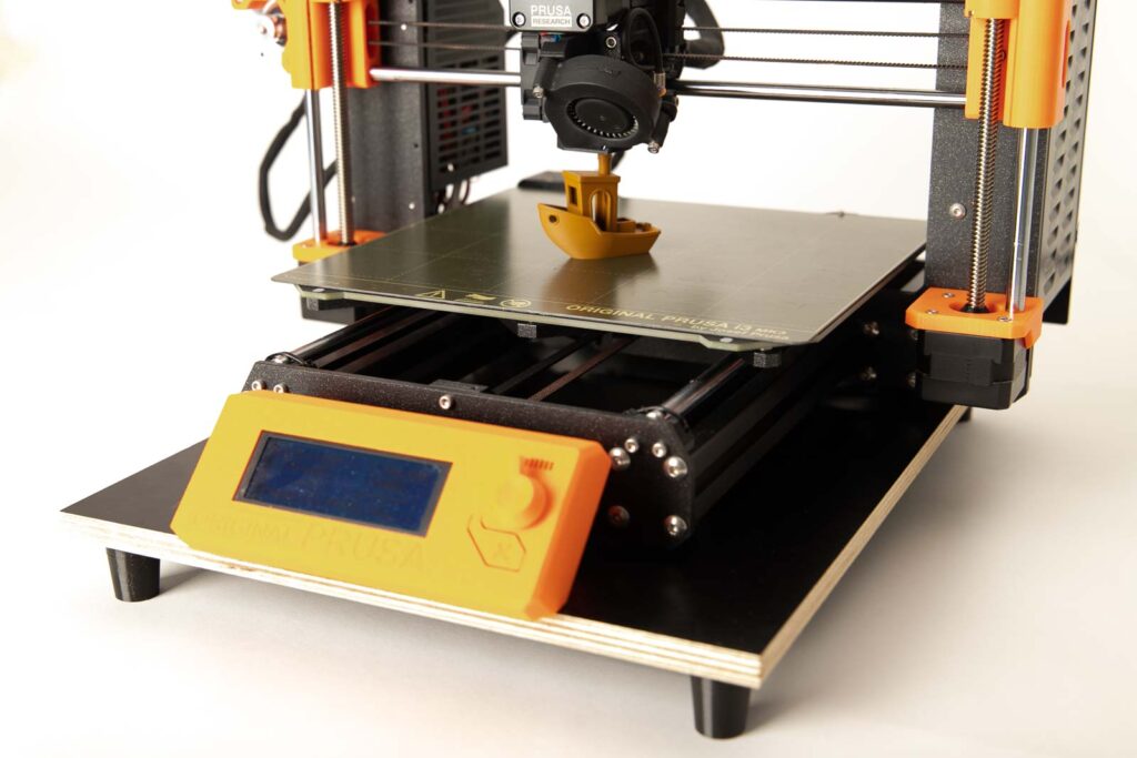
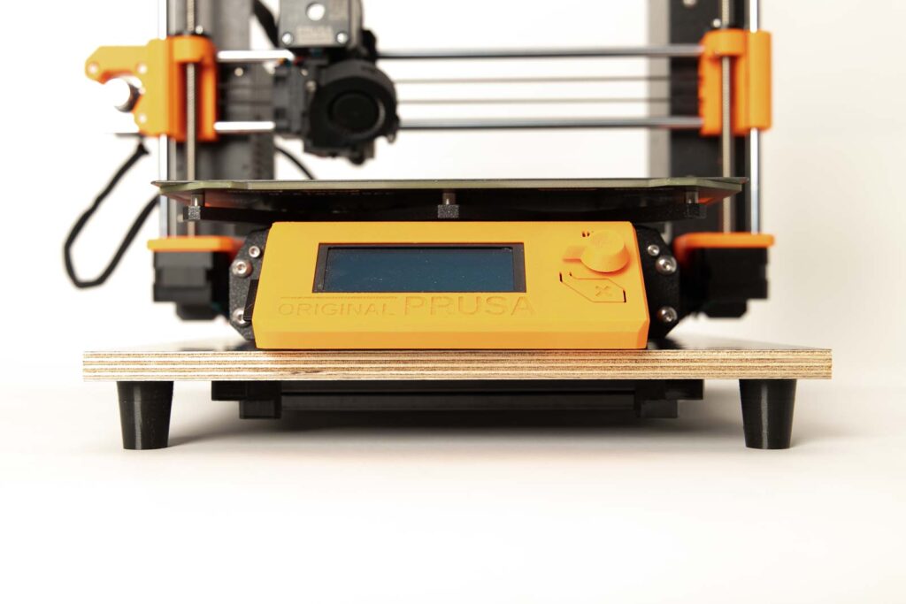
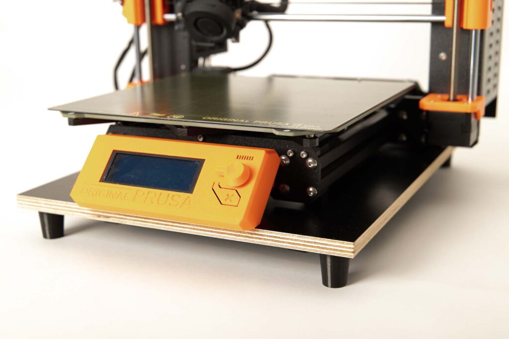
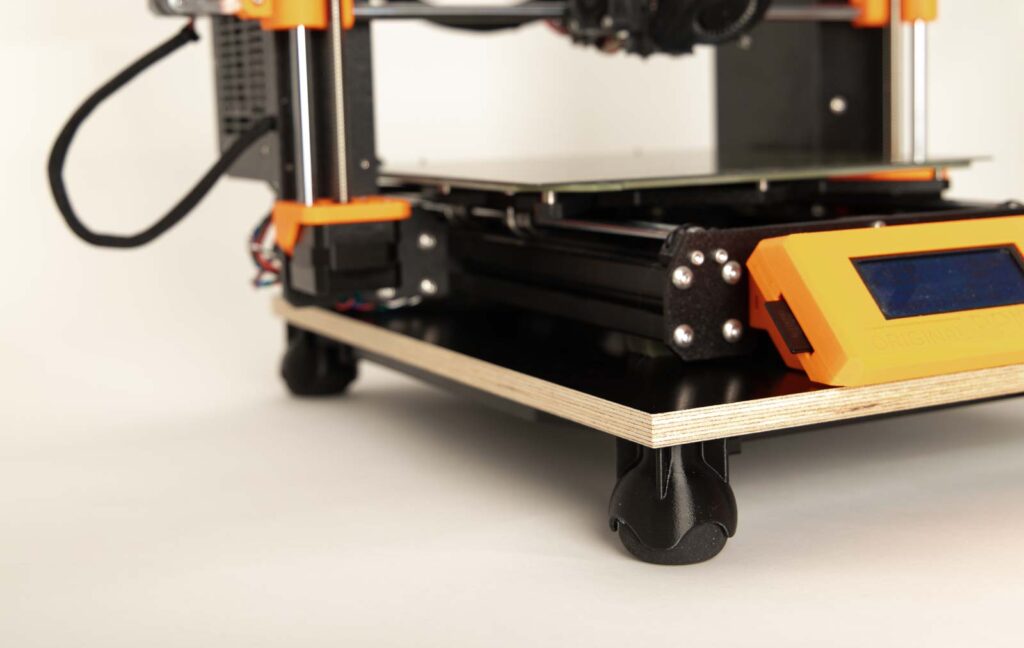
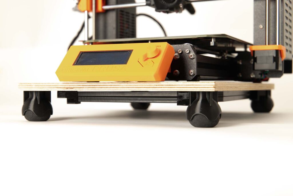
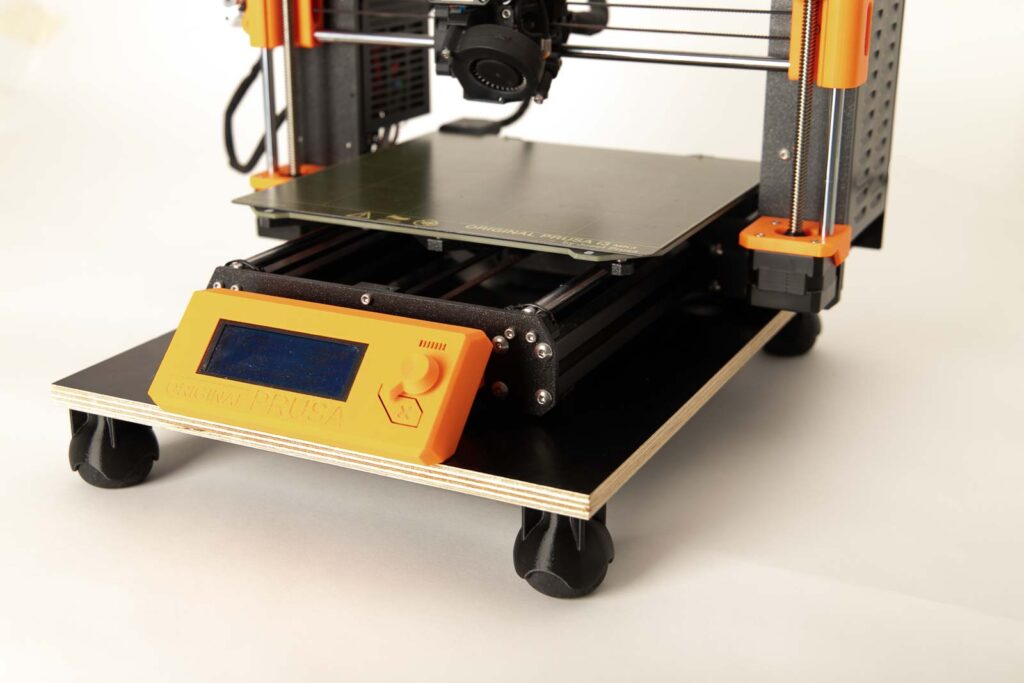
Below are more photos of the finished DIY damper board for your 3D printer, with flexible damper feet and with the squash ball dampers.
Disclaimer
The instructions and the associated files are an inspiration of Ingenieurbüro Dr. Janko GmbH to build this project yourself. Since Ingenieurbüro Dr. Janko GmbH has no way of checking and influencing the required quality of the printed components and purchased parts as well as the quality of the assembly and the correct functioning of the project or if any inadmissible changes and modifications to the project has been made, Ingenieurbüro Dr. Janko GmbH accepts no liability for functionality, stability or damage incurred by the project.
0 Comments