
How accurate is a FDM / FFF 3D printer? What does that have to do with tolerances? Why are fits important when you want to connect 3D printed parts?
In this article I explain what’s the thing with manufacturing tolerances of 3D printers and how this affects the connection of 3D printed parts and purchased parts.
3D printed parts do not fit together
Explained, using a 3D printed bolt as example:
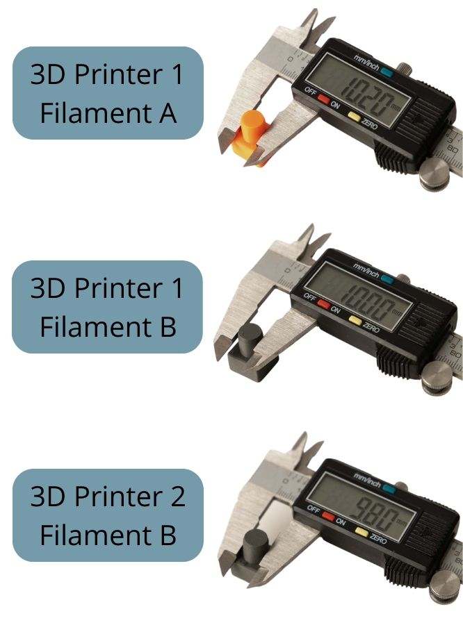
A 3D printed bolt should be 10 mm in diameter to fit into another part. The digital 3D print model (STL file) has a diameter of exactly 10.0 mm.
Your 3D printer 1 print the bolt with filament A. The part does not fit in the intended hole. After measuring, it turns out that the bolt diameter is 10.2 mm.
You print it again with filament B, now it is exactly 10.0 mm.
The same STL file then leads to a part with a diameter of 9.8 mm at a friend’s 3D printer 2 with filament B.
What happened to the 3D printed parts?
What happened with the bolt is because 3D printers print the digital files with certain dimensional deviations. These are given for FDM / FFF 3D printers at around +/- 0.2 mm, of course depending on many factors. Within this tolerance, FFF / FDM printer can print parts quite reliably.
In practice you can see the following: If a 3D print template (STL file) has a length of exactly 10 mm, for example, then the part printed from it will very likely be between 9.8 mm and 10.2 mm long.
Why are the dimensional deviations of the 3D printer so important?
For example, if a 3D printed bolt or a purchased part (e.g., a screw or a ball bearing) should fit exactly into a printed hole. If the hole is too big, the part will sit too loose, if the hole is too small, the part will not fit. The +/- 0.2 mm deviation, which appears relatively small, can have a major impact in this case.
That is of course annoying, either the digital 3D print model has to be readjusted or the settings in the slicer for the filament have to be changed. It’s particularly annoying when the printed parts don’t fit together after hours of printing.
But thanks to the PrintFit system, that doesn’t matter to you. Always print perfectly fitting parts with your 3D printing setup!
Why are there deviations in 3D printing?
The 3D printing process is extremely complex and influenced by many factors, many of which affect the final dimensions of the printed part.
Important factors for the form accuracy of 3D printed parts are:
- the basic calibration of the 3D printer,
- the perpendicularity of the axes to each other,
- the deviations of the individual layers in the Z-direction,
- the actual diameter of the filament,
- the accuracy and wear of the nozzle diameter,
- the settings in the slicer,
- the 3D filament used,
- the shrinkage of the material,
- the filament cooling,
- the printing temperatures and ambient temperatures,
- the print speed, and
- the absolute component dimensions.
Some individual factors are briefly discussed below.
Basic calibration of the 3D printer
The basic calibration is still very easy to understand. For example, the G code generated in the slicer tells the printer: Drive 30 mm! But instead, he drives 31 mm. The setting in the firmware of the 3D printer does not match here. The value set in the firmware of the 3D printer, which indicates how many millimeters a single step of the stepper motor is in the linear movement, is not correct.
This was often the case with home-built 3D printers in the past, but almost never occurs with modern desktop 3D printers.
The calibration of the 3D printer is checked with an XYZ test cube, see my article: Increasing 3D printer dimensional accuracy
Perpendicularity of the axes to each other
The alignment of the axes of the 3D printer to each other is particularly important for large 3D printed parts. Even very small angle errors result in skewed, warped parts. In the case of small parts, the alignment of the axes to one another is usually not very important.
It can be easily checked with a printed cube that is as large as possible and a good try square.
Deviations of the layers in the Z-direction
The repeat accuracy of the 3D printer along the Z-axis is particularly important here.
What do you mean with that?
A short example: With a cube to be printed, the 3D printer must move to the exact coordinates of the cube, from the first layer for each layer up to the top layer. If, for example, a driven belt is not properly tensioned or there is too much play somewhere in the mechanics, then the printer will not go to the exact points already approached in the previously layers. This means that the individual layers are not placed exactly on top of each other but are slightly offset. As a result, when the printed cube is finally measured, it will be wider in the X and Y directions than specified by the digital 3D model (STL file). Because here and there a few layers protrude beyond the actual contour of the cube.
If this is the case, it is best to check the mechanics of the axles for excessive play.
The actual diameter of the extruded plastic string
The diameter of the plastic string after the nozzle results from the interaction of the actual diameter of nozzle and filament, as well as the swelling of the plastic (filament).
The 3D printer gets the simple command “Turn by the angle XY” to extrude the filament. The extruder motor turns and pushes the filament into the heated nozzle. A thin plastic thread then comes out of the nozzle.
The exact diameter of this plastic thread depends on several factors. An average value is assumed in the slicer with the selection of the plastic type and the nozzle diameter. However, the actual value may deviate from this. However, the slicer calculates with the average value and this can lead to deviations in the component dimensions.
For example, the plastic string after the nozzle is thinner than calculated in the slicer, so the printed part will be smaller. The effect is particularly visible with thin webs.
Now what can lead to this?
- The actual diameter of the filament used
- The accuracy and wear of the nozzle diameter
- Swelling of the plastic after the nozzle
These factors are discussed in more detail below.
The actual diameter of the filament
The filament is never exactly 1.75 or 2.85 mm in diameter, these are usually manufactured with a tolerance of +/- 0.05 mm. If the diameter of the filament is now at the lower (1.70 mm) or upper tolerance limit (1.80 mm), this has a strong influence on the extruded plastic string. Increased or decreased flow by up to 11.4% according to Prusa. Since the calculation in the slicer is based on the normalized filament diameter of exactly 1.75 mm or 2.85 mm, this naturally has a strong influence on the dimensions of the printed parts.
Prusa with their own filament, the so-called Prusament, therefore manufacture even more precisely and remain below +/- 0.02 mm manufacturing tolerance.
The accuracy and wear of the nozzle diameter
The nozzle diameter is just like the actual filament diameter. It is never exactly manufactured, for example exactly 0.4 mm. It also wears out with the use of the 3D printer and is getting larger and larger over time.
Swelling of the plastic after the nozzle
Another very interesting effect is the swelling of the plastic after the nozzle. You can imagine it like this: The molten plastic of the filament is pressed with high force into the tiny nozzle, directly after the nozzle it is “free” again and widens or swells a little. This effect depends on many factors, including:
- the plastic material type,
- the nozzle geometry,
- the extrusion speed,
- the extrusion temperature,
- the moisture in the material
and even more.
To compensate for this effect, the flow rate (also known as extrusion multiplier) can be adjusted in the slicer. To do this, measurements are taken on printed test parts and adjusted in the slicer settings using the value of the flow rate. More on this in the article: Increasing 3D printer dimensional accuracy
Relationship between cooling and shrinkage of plastics
All influencing factors that have to do with the cooling speed of the plastics (filaments) used lead to another effect: the shrinkage – horror of all polymer technicians 😉
This effect is highly dependent on the type of plastic used (PLA, ABS, PETG, etc.), some plastics shrinking more and some less. ABS is one of the plastics that shrinks more, which in turn is reflected in the strong tendency for warping of the printed parts.
The shrinkage depends on the cooling rate. Explained relatively simply: When the plastic is heated in the extruder, the plastic expands and when it cools down on the print plate, it contracts again. So far quite simple if the cooling speed would not also play a role. If the plastic cools down very slowly, it contracts more than if it is cooled down quickly.
An example: A piece of plastic is heated and then allowed to cool very slowly, perhaps in a slowly cooling oven. This piece will have smaller dimensions at room temperature than the same piece of plastic that is thrown into cold water after it has been heated.
Why is that?
The long chains of molecules that make up plastics move more when the temperature of the plastic is high – the plastic expands. Then the plastic is cooled. If the molecular chains now have a lot of time due to slow cooling, they can lay together better and then take up less space in the material. If they are cooled quickly, they remain almost the same as in the heated state and take up more space, or the gaps between them remain larger. The space occupied is then reflected in the dimensions of the plastic part.
The next chapter 3D printing engineering fits is more about practical things that arise due to the dimensional deviations in 3D printing. Especially what the manufacturing tolerances mean for the design of 3D printed parts and how to deal with them when two parts are supposed to fit together.
3D printing engineering fits
As already mentioned, special problems arise due to the manufacturing tolerance of 3D printers for connections and their dimensional relationship to one another.
In mechanical engineering, such a dimensional relationship between two parts is called a fit. A distinction is made here between clearance, transition, and interference fits.
These three types will now be discussed in more detail below:
Clearance fit in 3D printing
The clearance fit is used wherever parts should still move relative to each other, i.e. still have “play”. Due to the manufacturing deviation of +/- 0.2 mm on each 3D printed part, the parts must be designed in such a way that they have a distance of at least 0.4 mm between the 3D models. Even better by a tenth of a millimeter more to 0.5 mm.
For example, a 0.5 mm gap is left between the 3D models of a bolt and part with a hole. The parts are printed but are at the upper extreme of the manufacturing tolerances, i.e., the hole is 0.2 mm smaller and the bolt 0.2 mm larger than in the 3D models. Then there is still a 0.1 mm gap between the two and the parts can theoretically still move towards each other.
However, if the two parts are at the lower extreme of the manufacturing tolerance, there is a gap of 0.9 mm between them. This is safe enough to move, but probably too much. The bolt can then tilt slightly, which is undesirable in some cases.
The PrintFit System was developed precisely for this case – different distances can be printed for critical clearance fits. For example, the 3D printed models of the bolt and the hole are only 0.2 mm apart, as the printed parts tend to be at the lower extreme. Or with a 0.7 mm gap, since the parts that are finally printed are at the upper extreme. In both cases you get a connection that has exactly the right play for your 3D printing setup.
Transition fit in 3D printing
As the name suggests, the transition between clearance and press fit is meant here. Depending on the dimensions of the 3D printed parts, a clearance or press fit is created. When this is the case is explained below using our example.
For example, the 3D printed models of the bolt and hole are both exactly 10.0 mm in diameter. Now the parts are printed, and the bolt is 9.9 mm in diameter and the hole is 10.2 mm. A clearance fit is thus created.
However, if the printed parts are on the other side of their manufacturing deviations, for example the bolt is 10.2 mm and the hole is 9.9 mm, then a press fit has been created that can only be joined with a lot of force – if at all.
This type of fit occurs, for example, when a ball bearing is to be pressed into a 3D printed part. The ball bearings already have a relatively low manufacturing tolerance and should not deviate by more than a few hundredths of a millimeter. The recess for the bearing is then exactly 22.0 mm in the 3D print template, for example with a 608 ball bearing (22x8x7). Depending on how the 3D printer prints that part in combination with filament and slicer, it is also exactly 22.0 mm or 22.2 mm or 21.8 mm.
- In the first case with the exact diameter of 22.0 mm, it can be pressed in well and also holds well.
- In the second case with the 22.2 mm recess, the connection is more in the area of a loose fit and the bearing easily falls out again.
- In the third case with the 21.8 mm recess, the bearing can no longer be pressed in by hand or the 3D printed part will be damaged if you press the bearing in.
The PrintFit System was developed precisely for this cases. There are several digital templates (STL files) of the same part with the recesses in 0.1 mm increments in the 3D print files. A trial part is printed and tested. If it is too difficult or too easy to press in the bearing into the 3D printed part, you can choose another 3D print template that has a larger or smaller recess and fits better.
Or a special PrintFit bearing tester is printed at the beginning and all the different recesses are tried out with the purchased bearing. The appropriate STL file can then be selected in the project by marking it on the tester. You can find the 3D print model for the 608 ball bearing tester here: Download PrintFit tester for 0 EUR
Press fit in 3D printing
The interference (press) fit is used to connect parts under high pressure. Due to the relatively large manufacturing tolerance of the FDM / FFF 3D printer, it is rather difficult to plan real press fits, which can also be used for 3D printing projects.
With the manufacturing tolerance of +/- 0.2 mm, the 3D printed parts to be joined would have to be very over or undersized. In our example, the bolt is at least 10.2 mm in diameter and the hole is 9.8 mm in diameter.
- In the first extreme case, the parts are both exactly 10.0 mm and can still be connected by hand with some force.
- In case the printed parts correspond exactly to the templates, the bolt is 10.2 mm and the hole is 9.8 mm. Most likely you cannot apply enough force to join them by hand and an additional press would be needed.
- At the other extreme, the bolt is 10.4 mm and the hole is 9.6 mm. There is a high probability that the parts are going to destroyed when joining with a hydraulic press.
In the case of metal parts, the thermal expansion of the parts is often used when pressing some parts together. So, the part with the hole is heated and the bolt is cooled. However, such methods and hydraulic presses are rather unsuitable for DIY projects.
You made it this far, really persistent 😀 – congratulations! Do you have any other thoughts on 3D printer accuracy or fits, let me know and comment below.
0 Comments