
Nothing is more annoying than when two 3D printed parts do not fit together after hours of printing or a purchased part does not fit into the 3D printed part. I got the solution to these problems:
➔ the PrintFit System
PrintFit means that there are 5 slightly different 3D print models for a part.
For example, there are 5 different STL files for a nut in which the thread is gradually designed from narrow to wide. This makes it extremely easy to find the perfectly fitting 3D printed nut, even if your 3D printer is not exactly calibrated.
To do this, print the standard 3D printing model suggested in the instructions. If the resulting connection is:
- too narrow, then simply print the next larger STL file
- too loose, then the next smaller STL file
Optionally, you can also simply print one of the PrintFit testers that can be downloaded here. All implemented dimensions are available on this. Since the testers are relatively small, you can quickly print them out and test them right away. This will help you find the optimal gaps and fits for your 3D printed parts. In the STL files of the 3D printing project, you then select the appropriate STL file.
Introduction to PrintFit
3D printed parts for a complex project are designed in such a way that they later fit together well. For example, enough play in threads and no play in press fits. But the final dimensions of the printed parts depend on many factors. So, depending on the 3D printer and setup, some printed parts may be larger or smaller than specified in the digital templates.
To be able to deliver exactly the parts that fit together perfectly for every 3D printer setup, I came up with the PrintFit System. Soon it will be available for all 3d print projects on 3D-PRINT-FILES. Every critical part will be available in several versions with slightly different dimensions, so that they always fit perfectly together.
If you like to design 3D printing projects yourself, the system is of course open to everyone. Test your 3D print setup with the various PrintFit testers and then design the connection with the gap that suits you best. Or publish your project with slightly different STL files like me, so everyone can use the best fitting model when printing your project.
Here you find all the details about the connections, construction, the gap dimensions used and much more information about the system.
The PrintFit System
Here you find the most important connections for 3D printing. With the corresponding dimension tests to download, you can find out which dimensions are best for your 3D print setup.
Design the right connection right away or always print out the right components from my 3D printing templates. This saves time and material and spare your nerves.
It’s best to subscribe for the newsletter list right away and download all the 3D printing testers, as well as the Excel file to enter the results.
All relevant PrintFit testers are also included in the 3D print files of the projects. Simply test in advance which gap or dimensions suits your combination of 3D printer, filament, and slicer settings best. Then print the STL file with the dimensions that did best with the tester.
Or test one 3D print model of the project directly with the standard dimensions. The printed part did not fit? Then simply print the next larger or next smaller available 3D print model (STL file). Avoid trouble and time-consuming trial and error with the scaling function in your slicer.
Also test your purchased parts in which 3D printed part they fit best to save time and trouble.
Supported 3D printing projects
The first projects to be supported are the new 2023 versions of the Filament Box and the Silica Gel Box:
- DIY filament dry box
- DIY silica gel box (Add-on for the Filament Box)
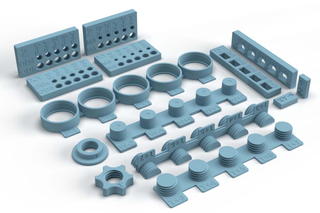
Overview of the individual connections and testers
Join 3D printed parts together
- 3D printed Z thread (standard Z direction)
- 3D printed XY thread (improved split shape in XY direction)
- 3D printed wedge / cone clamp connection
- Print-in-Place 3D printing – rotatable insert
- 3D print tester for sliders – all variations
Connect 3D printed parts with purchased parts
- Metric screws into a 3D printed part
- Put a PTFE tube through a 3D printed part
- Pressing 608 ball bearings into a 3D printed part

When 3D printing the PrintFit parts, the following applies:
Always print with the same filament, 3D printer and slicer settings (speed, layer height, infill, etc.) as for the later 3D printing project!
Join 3D printed parts together
3D printed Z thread – Classic (standard Z-direction)
A very practical way to connect 3D printed parts is the 3D printed screw connection. One part has internal threads, such as a nut. A second part with an external thread, like a 3D printed screw, is then screwed into the first part. The easiest way to print the threads is when the longitudinal direction of the thread is in the Z-axis of the 3D printer. So in the 3D printing process, the screw and nut grow upwards.
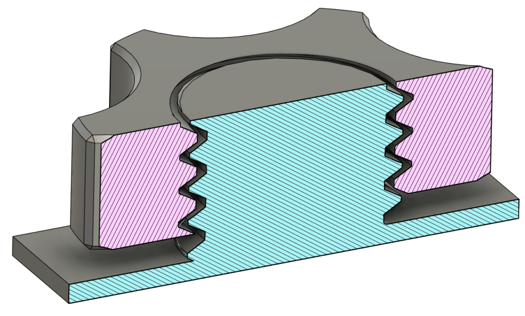
When I model a 3D printing thread, I use the classic metric ISO thread. To ensure it fits together, I am adjusting the gap between the internal and external thread.
The gaps from the standard metric threads are too narrow for 3D printed parts, so the distance between the screw and the nut is widened.
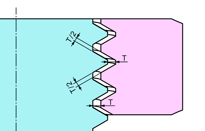
In the 3D printing models, the threads are designed with T= 0.3 mm to T= 0.7 mm radial gaps. The STL files are then marked with T+3 to T+7. The T stands for thread and the numbers indicate the gap at the radius in tenths of a millimeter.
In the 3D print model, the thread with the following marking corresponds to:
- T+3 a 0.3 mm gap (T= 0.3 mm)
- T+4 a 0.4 mm gap (T= 0.4 mm)
- T+5 a 0.5 mm gap (T= 0.5 mm)
- T+6 a 0.6 mm gap (T= 0.6 mm)
- T+7 a 0.7 mm gap (T= 0.7 mm)
Test the 3D print setup for Z threads with PrintFit benchmark
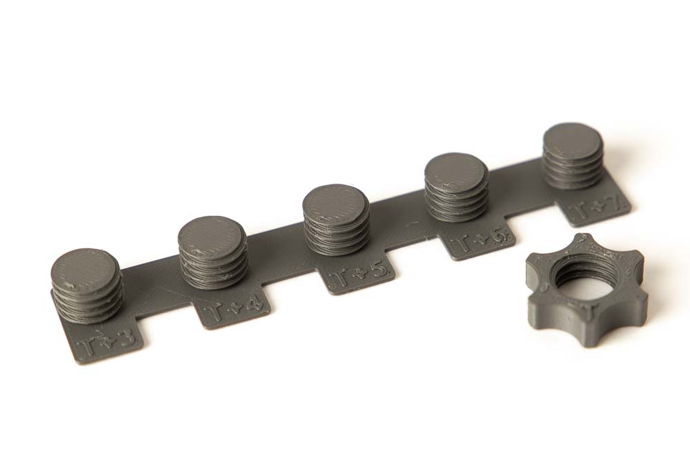
Print the 3D print templates (STL files) PrintFit_Z-Thread and PrintFit_Nut with the same filament and settings as for the later project.
The threads on the tester plate correspond to an M12 x 1.75 metric thread, with adapted gaps between the internal and external threads.
The nut is marked with a T for top on the top.
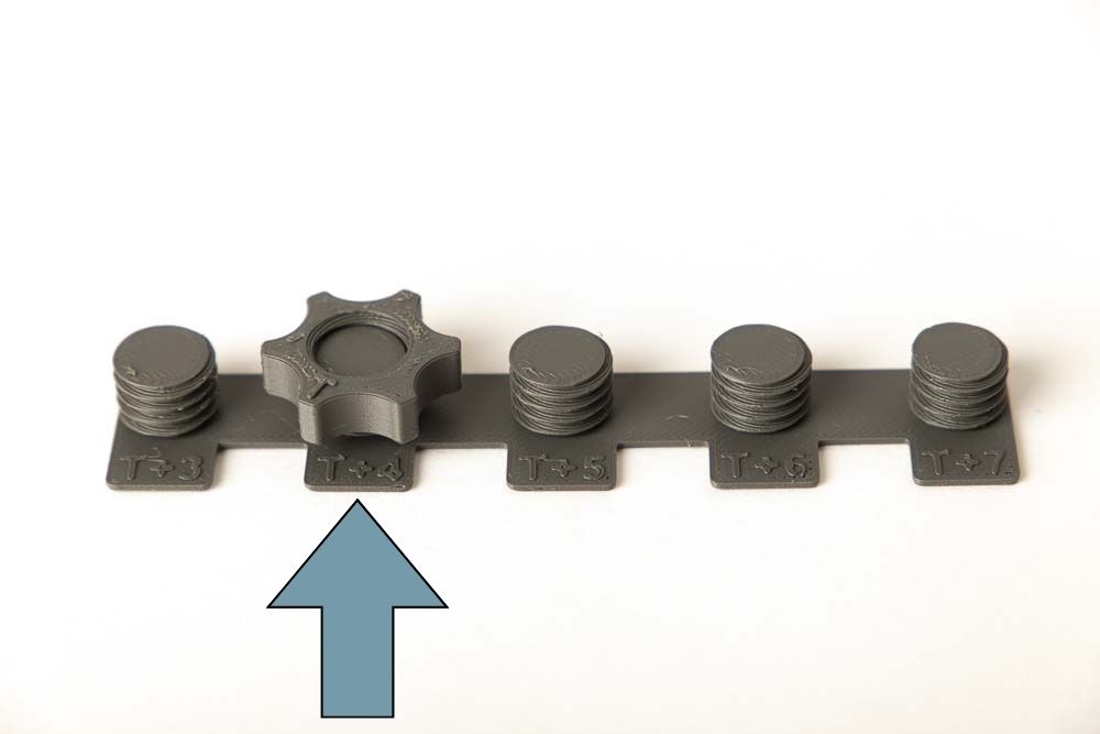
Screw on the 3D printed nut onto the threads and check on which one it fits easy but isn’t too loose. So, you get the best gap between nut and screw.
For example, at T+4 the 3D printed nut fits best. So, the radial gap of 0.4 mm is best for the tested combination of your 3D printer, filament, and slicer settings.
Also test whether it makes a difference if the nut is screwed on with the T symbol up- or downwards. If it is more difficult with the T upwards, there is most likely an elephant foot 3D print issue. Martin from the3dprinterbee.com has written a good article on how to identify and fix this error.
3D printed XY thread – Strengthened by alignment (XY Direction)
A disadvantage of classic 3D printed threads is that due to the layered structure in 3D printing, prints have lower strength in Z-axis. And at classical 3D printed screws this is the direction of the later applied force. As a result, printed screws, which are usually subjected to tensile loads in the longitudinal direction, are a lot weaker than it would be possible with the material.
The solution to this problem is to split the threads in the middle and place them flat on the 3D printer’s build plate. As a result, the longitudinal direction of the screw is aligned in the X or Y direction and the finished 3D printed screw benefits from the higher strength of the printed parts in these directions.
After 3D printing, the two halves are simply folded together and can be screwed in immediately. If desired, the halves can also be glued together in the middle with a drop of super glue.

To aviod that the halves fall apart after removing from the print plate, they are connected with a narrow bar that is 0.2 mm high and 0.5 mm wide. When folding the thread halves together, the bar is bent together.
Test the 3D print setup for split XY threads with the PrintFit tester
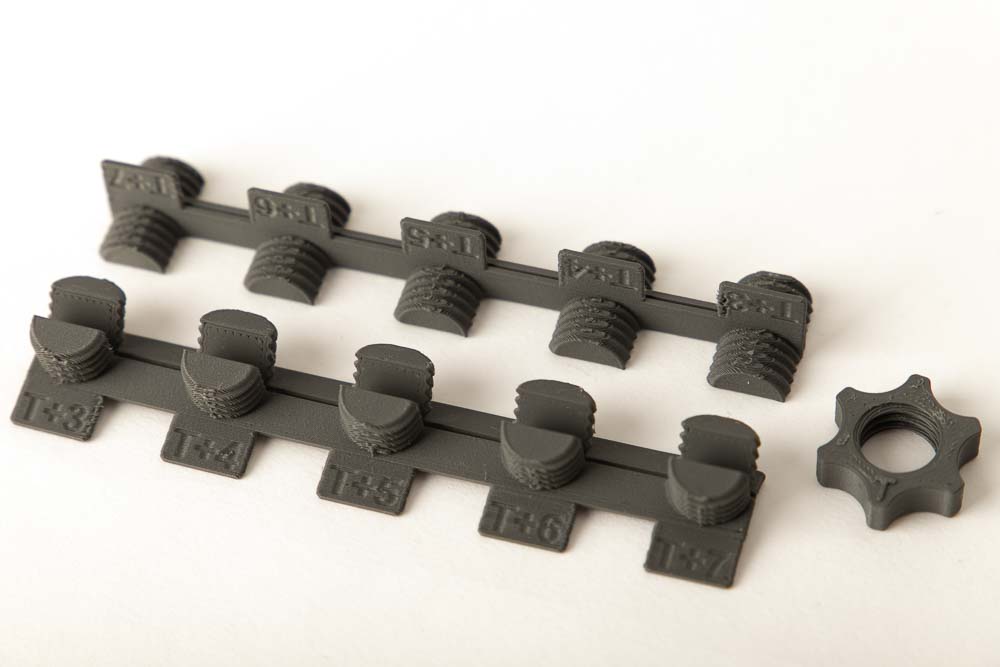
To do this, print the STL files PrintFit_XY-Thread and PrintFit_Nut with the same filament and settings as for the later project.
After printing, fold the two halves of the thread together. If desired glue them together with super glue. But this is not necessary, the nut also holds the two halves together.
Then test which thread the nut fits best, the threads are marked with T+3 to T+7. As with the classic Z-thread this means:
- T+3 a 0.3 mm gap
- T+4 a 0.4 mm gap
- T+5 a 0.5 mm gap
- T+6 a 0.6 mm gap
- T+7 a 0.7 mm gap
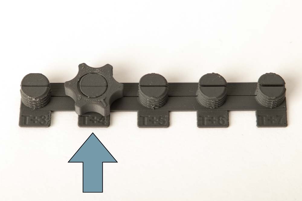
Screw the nut onto the 3D printed threads and check on which one it fits easily but is not too loose. This is then the best gap between nut and bolt.
If this is the case with T+4, for example, the radial thread gap of 0.4 mm is best for the tested combination of 3D printer, filament and slicer settings.
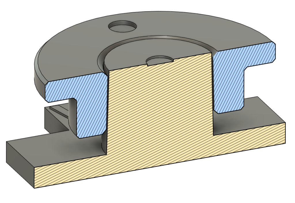
3D printed wedge / cone clamp connection (Z-direction)
The layers created in the FDM / FFF 3D printing process automatically result in a rough surface in the Z direction of the 3D printed parts. This can be used to create very tight clamp connections.
A slight incline is constructed on the parts to be connected in the Z direction. If the parts are now plugged into each other, they snap into each other and are almost impossible to separate.
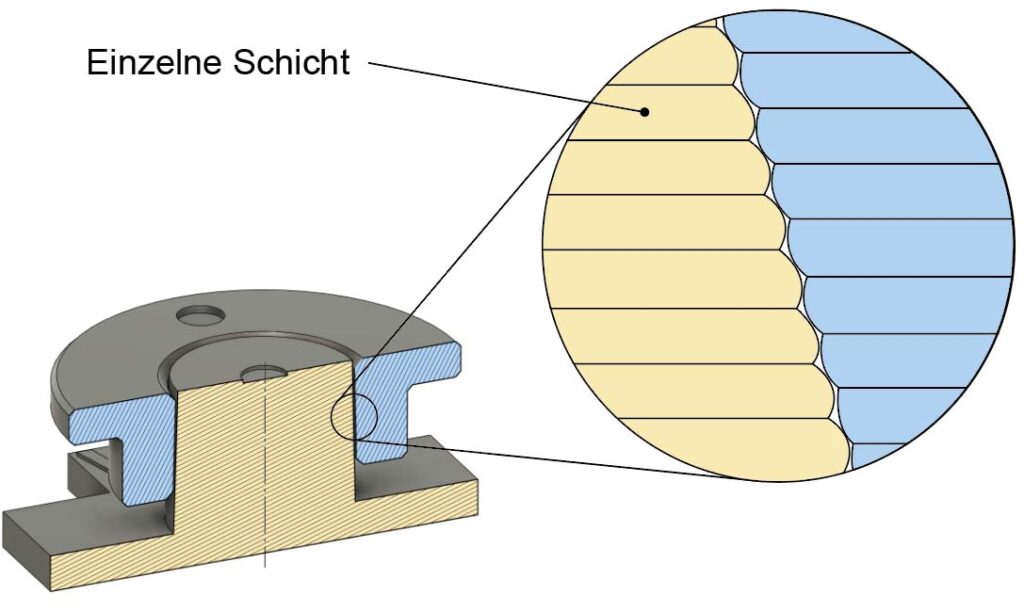
The clamping ring and the cone are printed in the Z direction in such a way that the individual layers interlock when the two 3D printed parts are placed on top of each other.
If the diameters of these parts deviate from one another, the system will still work, but the parts will no longer be flush on the top with one another.
Therefore, there is the possibility in the PrintFit System to print parts with different resulting gap dimensions.
The cone and the clamping ring both have a 3 degree bevel, ideally they are firmly connected when the top surface of the cone is flush with that of the clamping ring.
To define the orientation of the clamping ring clearly, it has an embossed circle on the side that is later to be flush with the top of the cone. The top of the cone has the same symbol stamped on it.
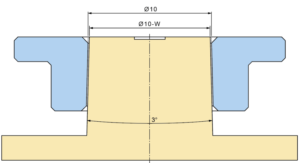
The different gap dimensions of the PrintFit cone tester result in the 3D printed models when the clamping ring is attached flush. They are marked with a W, which stands for wedge, and numbers that indicate the gap in tenths of a millimeter.
So, the following designations correspond to:
- W+2 for a 0.2 mm gap between diameters
- W+1 for a 0.1 mm gap between the diameters
- W+0 no gap between the two parts
- W-1 for an overlap of 0.1 mm between the diameters
- W-2 for an overlap of 0.2 mm between the diameters
Test the 3D print setup for clamp connections with the PrintFit tester
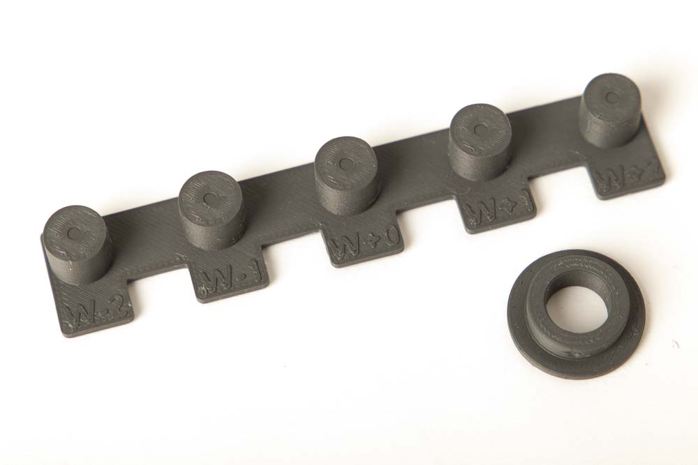
To do this, print the 3D print files PrintFit_Cones and PrintFit_Clamping_Ring with the desired filament and 3D print settings.
The clamping ring has an arrow embossed on the side that indicates the plug-in direction. The cone test plate has 5 cones with different diameters.
Starting with W+2, a test is then made to see whether the clamping ring can be pushed onto the respective cone with a little force and whether it closes flush. Do not use too much force when testing it for the first time, the connection is very tight and may not be loosened any more.
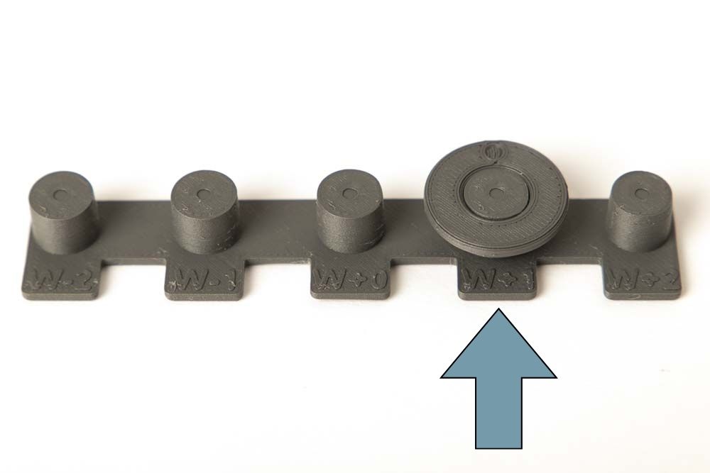
The optimal gap for your 3D printing setup has been found when the clamping ring sits flush on the cone with a little force and is difficult to loosen again.
As in the picture it happens with W+1, that means the cone has a diameter of 9.9 mm at the top and the clamping ring has a diameter of 10.0 mm.
Print-in-Place 3D printing – rotatable insert
A particular benefit of 3D printing is the ability to print parts within parts. This means that a finished product with various integrated functions can be created in just one printing process.
An important design detail is the gap between the parts. It is also very important how the form fit is designed, so how the parts are prevented from simply falling apart after being detached from the printing plate.
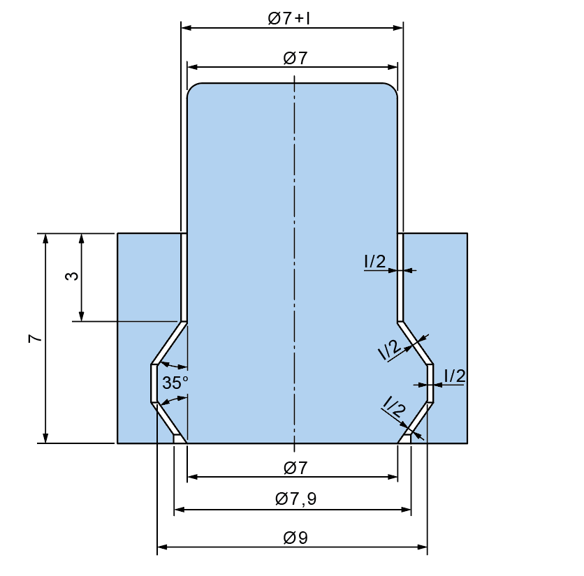
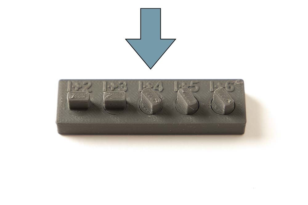
The form fit is very easy to achieve with two slopes, one at the top and one at the bottom, as shown in this tester. The gap between the rotatable insert and the base part must now be chosen so that the insert can be rotated but not too large so that the insert does not tilt and wobble too much.
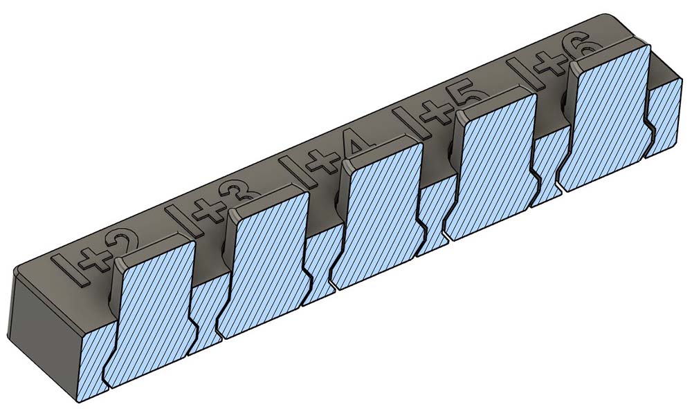
Five print-in-place inserts are designed into the PrintFit tester. So, five different gap dimensions are modeled between them and the base part. The inserts are marked from I+2 to I+6. The I stand for insert and the corresponding number indicates the gap on the diameter in tenths of a millimeter.
So, between the insert and the base part there is a gap of:
- 0.2 mm in diameter at I+2 (I= 0.2 mm)
- 0.3 mm in diameter at I+3 (I= 0.3 mm)
- 0.4 mm in diameter at I+4 (I= 0.4 mm)
- 0.5 mm in diameter at I+5 (I= 0.5 mm)
- 0.6 mm in diameter at I+6 (I= 0.6 mm)
Use the PrintFit benchmark tester to find the best 3D print setup for a print-in-place rotatable insert
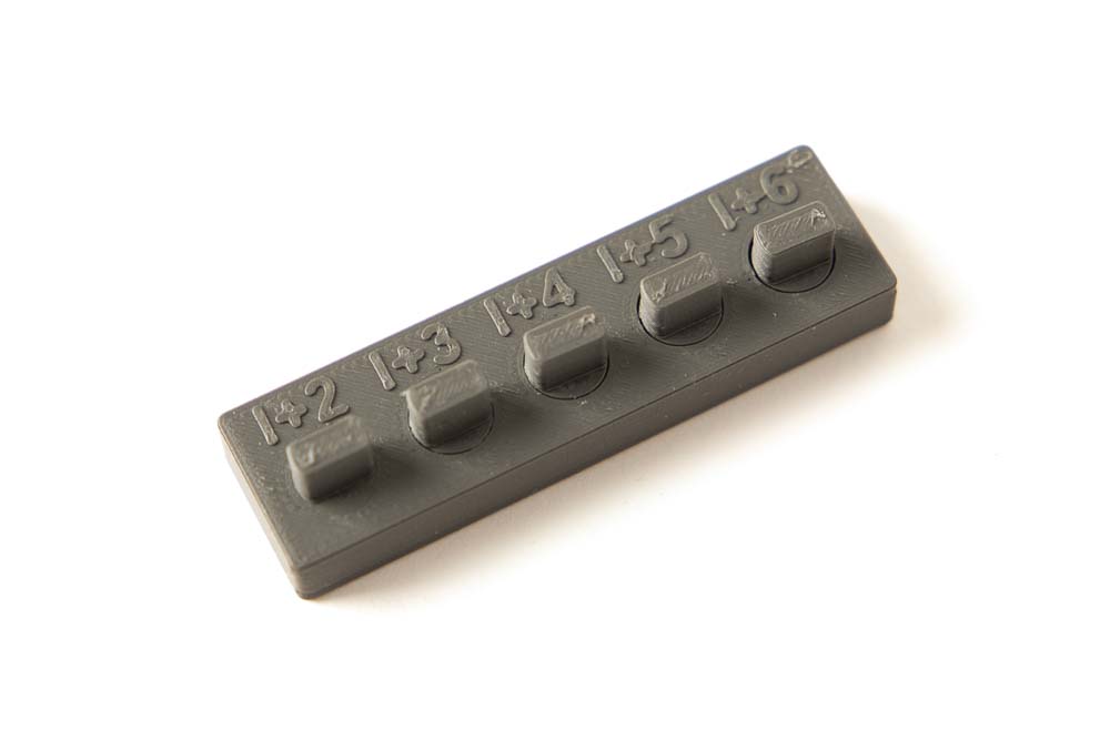
Print the 3D print template PrintFit_Turnable_Insert with the desired settings.
After printing the tester, check the underside (side that was connected to the printing plate) to see whether there are any material residues sticking the turnable inserts and the base part together. If that’s the case: try whether the parts can be separated from each other with a carpet knife or scalpel.
Then test which turnable inserts can actually be rotated. Sometimes some force is needed to pull it loose, but you should be able to do it by hand. Try the rotatability of the inserts one after the other.
The appropriate gap is the smallest at which the insert can be rotated, as here with the tested settings it is at I+4.
3D print tester for sliders – all variations
In some cases, 3D printed components are required to fit into one another, but should still move in one direction. The challenge is then to not completely close the gap between the two 3D printed parts. The gap between the two parts could be
- too small (parts can no longer move towards each other) or
- too big (parts wobble or tilt)
in the resulting 3D printed parts.
To test your 3D print setting for that type of connection, get the benchmark PrintFit 3D printing parts that can be used to decide how large the gap should be. Since the dimensions depend on the positioning of the parts in the 3D printer, both, the base and inserts are available in XY and Z orientation.
Test the 3D print setup for slider inserts with PrintFit benchmark tester
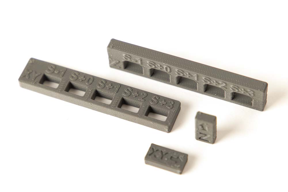
Depending on how the slide mechanism will be printed later, select the appropriate testers with the same orientation.
If, for example, the opening for the slide is later printed standing (i.e. in the Z direction) and the slide lying on the printing plate (i.e. in the XY direction), then print the parts PrintFit_Slider_Base_Z and PrintFit_Slider_Insert_XY.
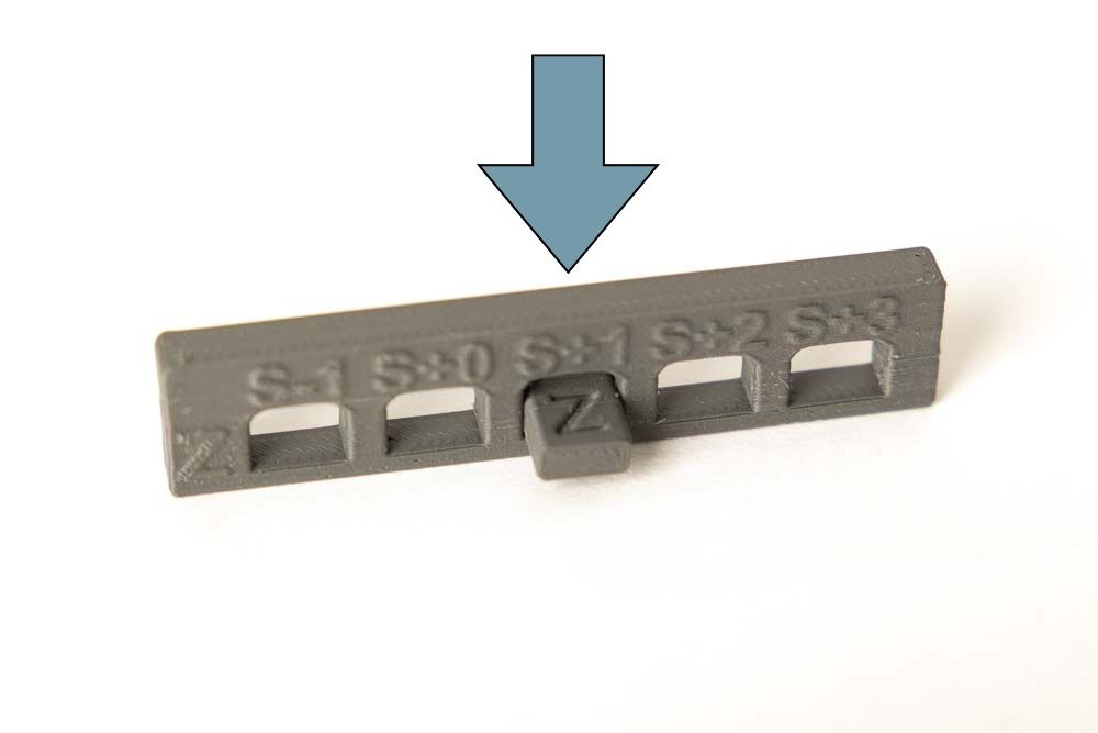
The 3D print files of the base parts have five openings, the width of which varies. They are marked with S for slider and numbers that indicate the theoretical gap between opening and insert model in tenths of a millimeter.
So, S+2 corresponds to a 0.2 mm gap between slide and opening, S+0 no gap and S-1 an overlap of the two parts by 0.1 mm. The inserts are always 8 mm wide, so the openings in the base parts are accordingly to the following labels:
- S-1 = 7,9 mm
- S+0 = 8,0 mm
- S+1 = 8,1 mm
- S+2 = 8,2 mm
- S+3 = 8,3 mm
wide.
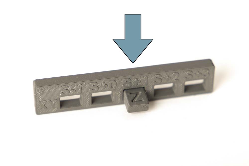
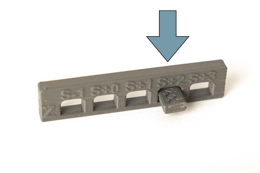
Print the required testers and then try to slide the insert into the openings on the base part. If the connection is not too tight or too loose, the right gap has been found. In this example the gaps are between 0.1 mm and 0.2 mm, depending on the combination of the oriented parts.

Connect 3D printed parts with purchased parts
In addition to connections between 3D printed parts, connections to purchased parts such as screws, nuts, ball bearings or PTFE tubes are also of great interest for 3D print projects. These purchased parts can of course also have different dimensions that are larger or smaller than stated due to their manufacturing tolerances or quality.
For example, the diameter of screws from manufacturer A are 0.2 mm larger than from manufacturer B. Where screw A can be screwed easily into a 3D printed part, this does not work with the screw from manufacturer B.
Metric screws into a 3D printed part
The easiest way to connect a 3D printed part with purchased screws is to simply screw them into a printed hole. To do this, the printed hole must be slightly smaller than the outer diameter of the screw’s thread. The metal thread of the screw then simply cuts its own thread into the 3D printed plastic part.
Since both, the outer diameter of the screw and the diameter of the printed hole can vary due to production, there is a PrintFit tester for it. At the moment only M3 and M5 screws are used in the 3D printed projects, so only these are available for the time being.
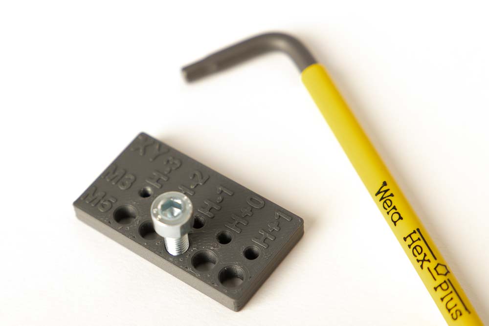
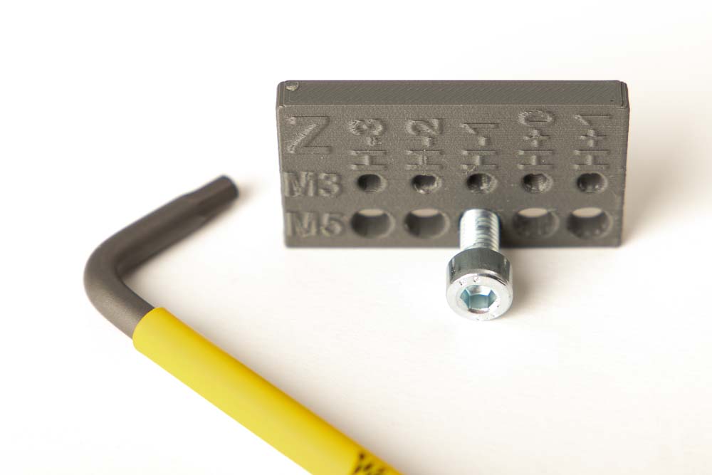
PrintFit screw-in benchmark tester for metric screws
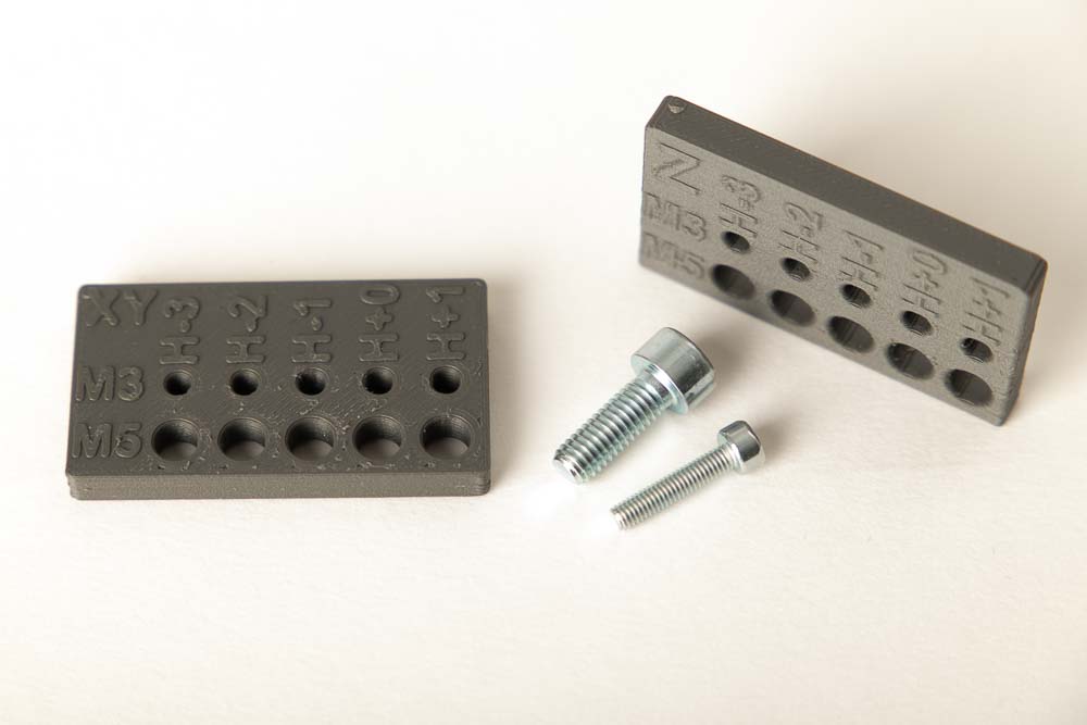
Depending on how the later hole is oriented in the printing process – at a right angle to the printing plate (XY) or at the side of a 3D printed part (Z) – select the appropriate tester.
The testers have 5 holes with slightly different diameters for the screw diameters. These are marked with an H for hole and a number that indicates the deviation from the standard screw diameter in tenths of a millimeter.
This means in the digital 3D printing models:
- H-3 is a bore with 2.7 mm for M3 and 4.7 mm for M5
- H-2 is a bore with 2.8 mm for M3 and 4.8 mm for M5
- H-1 is a bore with 2.9 mm for M3 and 4.9 mm for M5
- H+0 is a bore with 3.0 mm for M3 and 5.0 mm for M5
- H+1 is a bore with 3.1 mm for M3 and 5.1 mm for M5
Print the appropriate tester PrintFit_M3_M5_Screws_Z or PrintFit_M3_M5_Screws_XY with the desired settings and filament. Then try to screw a M3 or M5 screw into the printed holes, starting from the largest hole (H+1). The best fit is found when the screw can be screwed into the bore with not too much effort, sits firmly and is held securely.
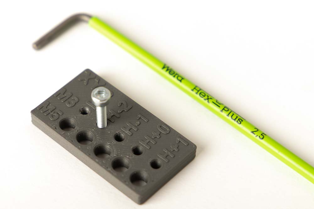
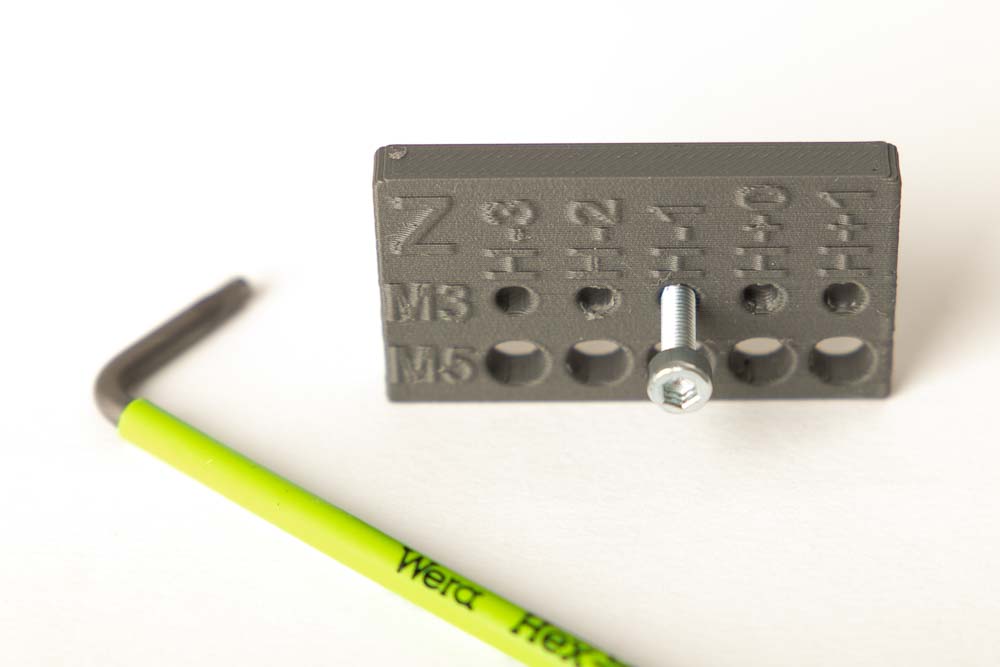
The result can vary with screws from different manufacturers, always use the screws that you are going to use later in the 3D printing project.
Put a PTFE tube through a 3D printed part
PTFE tubes are ideal for transporting 3D printing filament, which is why they are used in the filament dry box and the 3D printer housing, for example.
Standard tubes used in the 3D print projects got an outside diameter of 4 or 5 mm, the actual diameter can vary slightly depending on manufacturing tolerances. The PrintFit tester for PTFE tubes can be used to quickly determine what diameter a printed hole should have that a PTFE tube is able to pass through.
PrintFit PTFE tube tester
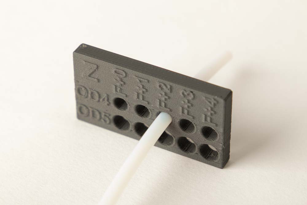
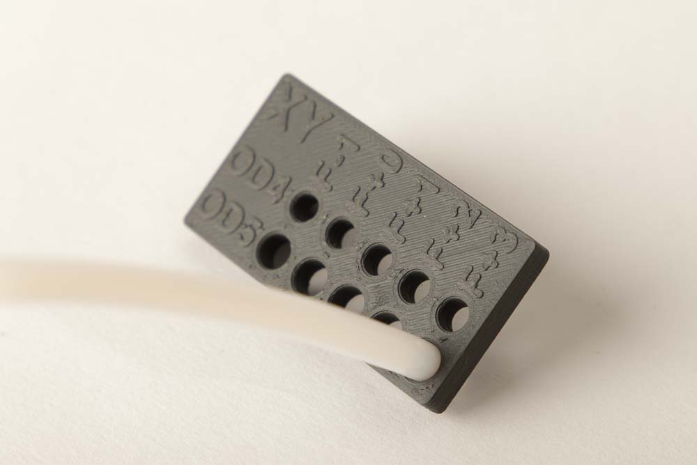
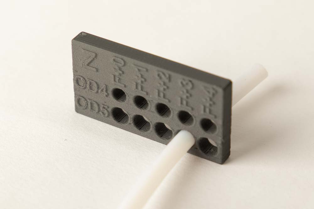
Again, it makes a difference how the hole is oriented on the printing plate. Does its axis point up and the tester “lays” on the build plate (XY) or is the bore axis parallel to the plate and the tester “stands” on the heatbed (Z). There are separate testers for both variants, which are marked with a XY or a Z.
In addition, the diameter range covered by the testers is slightly different. Due to the necessary covering (bridging) of the hole with material, the holes in the Z variant are always slightly smaller and larger diameters are required.
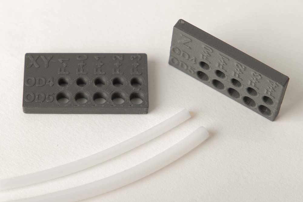
The testers have two rows with different bores. These are marked with OD4 and OD5, which stand for the two usual used outer diameters of 4 mm (OD4) and 5 mm (OD5).
The different hole diameters are marked with an F for fit and a number that indicates the deviation from the standard diameter in tenths of a millimeter.
In the STL file, this means:
- F-1 is a hole of 3.9 mm for OD4 and 4.9 mm for OD5
- F+0 is a hole of 4.0 mm for OD4 and 5.0 mm for OD5
- F+1 is a hole of 4.1 mm for OD4 and 5.1 mm for OD5
- F+2 is a hole of 4.2 mm for OD4 and 5.2 mm for OD5
- F+3 is a hole of 4.3 mm for OD4 and 5.3 mm for OD5
- F+4 is a hole of 4.4 mm for OD4 and 5.4 mm for OD5
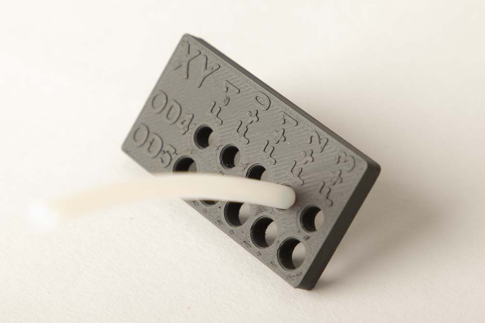
Print the PTFE tube tester PrintFit_PTFE_Tube_XY or PrintFit_PTFE_Tube_Z with the desired settings and filament. Then try to put an OD4 or OD5 tube through the holes, starting from the largest hole (F+3 or F+4). The best fit diameter is found when the tube can be pushed through easily with not too much effort.
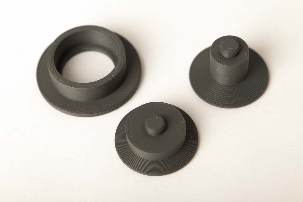
Pressing 608 ball bearings into a 3D printed part
In addition to screws, ball bearings are also a very important purchasing part for 3D printing projects. The easiest way to fix it, is to press the bearing into a 3D printed part. However, just a few tenths of a millimeter decide whether the bearing cannot be pressed in at all or is too loose and falls out of the 3D printed part again.
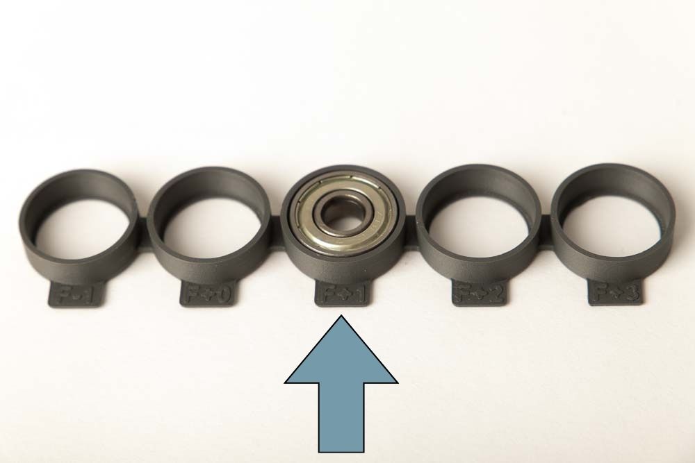
PrintFit 608 ball bearing benchmark tester
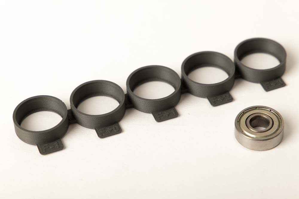
The tester is very simple, there are again five openings with slightly different diameters. The openings are marked with an F for fit and a number that indicates the deviation from the standard diameter of the bearing in tenths of a millimeter.
The 608 ball bearing has an outside diameter (OD) of 22 mm, so the numbers refer to this.
In the STL file, this means:
- F-1 has a diameter of 21.9 mm
- F+0 has a diameter of 22.0 mm
- F+1 has a diameter of 22.1 mm
- F+2 has a diameter of 22.2 mm
- F+3 has a diameter of 22.3 mm
To find the ideal diameter for your 3D printing setup, print the model PrintFit_608_Bearing_OD22_XY with the desired settings and filament.
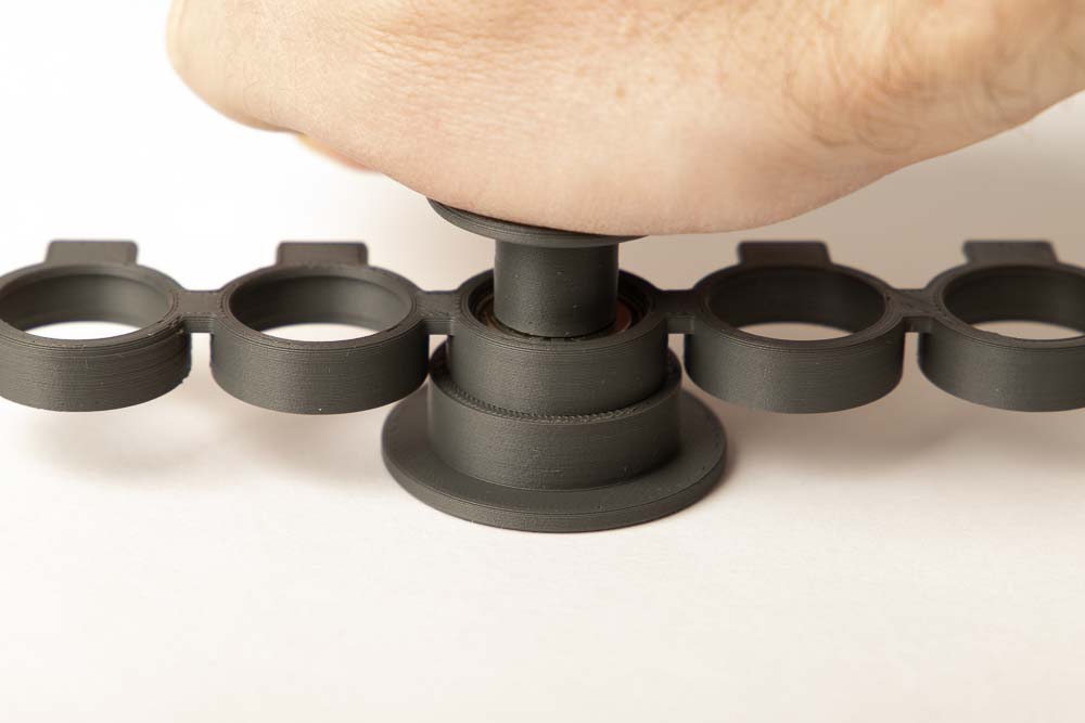
For easier handling when pressing the bearings in and out of the 3D printed tester, it is also recommended to print the 3D printed tools: Tool_Bearing_Press_In, Tool_Bearing_Press_Out and the Tool_Bearing_Press_Counter.
Then insert a ball bearing starting at the largest opening (F+3) and test whether it can be pressed in. If it is too easy to press in and the bearing does not sit tight afterwards, continue with the next smaller opening.
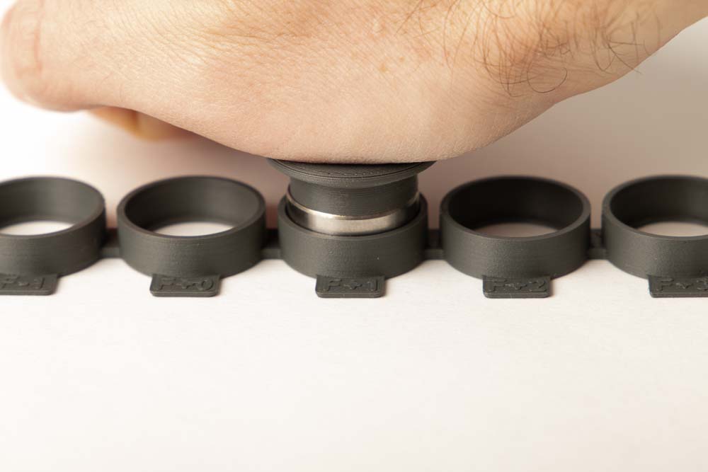
Use the 3D printed press-in tool. To do this, place it in such a way that the centering tip sinks into the ball bearing bore and the pressing surface lies flat on the ball bearing. Then press on the press-in aid with the heel of your hand.
To press the bearing out again, use the press-out tool and the press counter, instructions for pressing out can be found here: Pressing a 608 ball bearing out of a pulley.
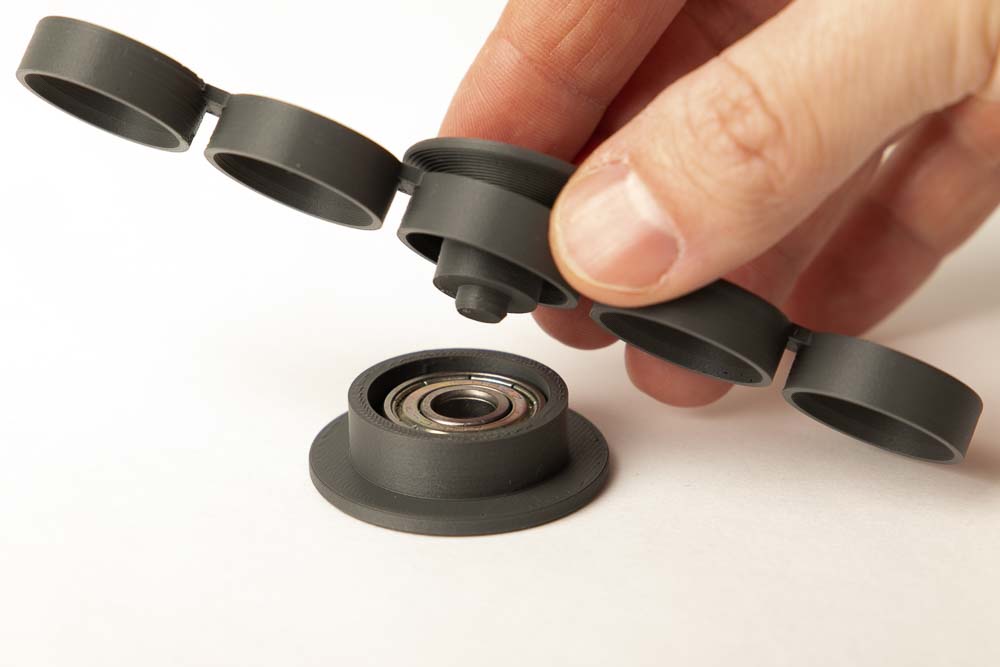
The right opening for your 3D printing setup has been found when the bearing can still be pressed in with manageable force and then sits firmly and securely.
Note the identification of this opening and print the corresponding project 3D printing file.
In this example, this is the case at F+1 (at a diameter of 22.1 mm).
Enter the determined values in the associated Excel sheet
The files (Download PrintFit tester for 0 EUR) also contains an Excel file in which you can enter the values you have determined. This is handy for noting down your settings and results, and to use them later for other projects.
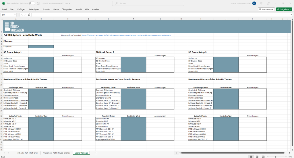
You can of course adapt the file as you need it, I will briefly explain the basic thoughts here:
A new worksheet is created for each tested filament. In the downloaded Excel file, two filaments that I use are already created for demonstration purposes.
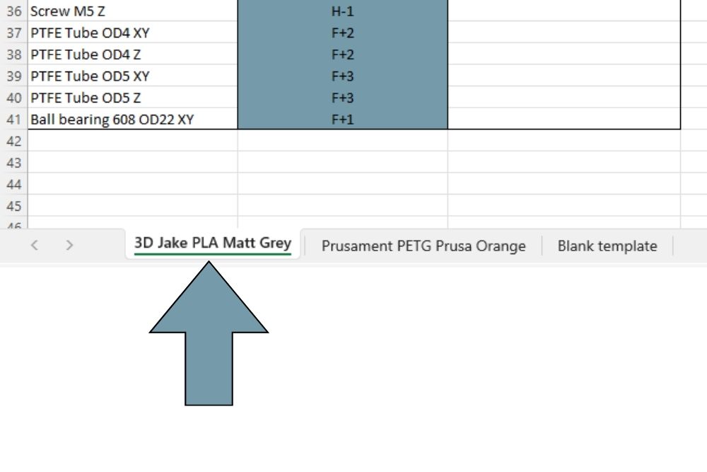
You can find the worksheets at the bottom left of the Excel window. A blank template is created as the third worksheet.
Then simply delete the two example filaments and enter your own results. They only serve as example for saving the results.
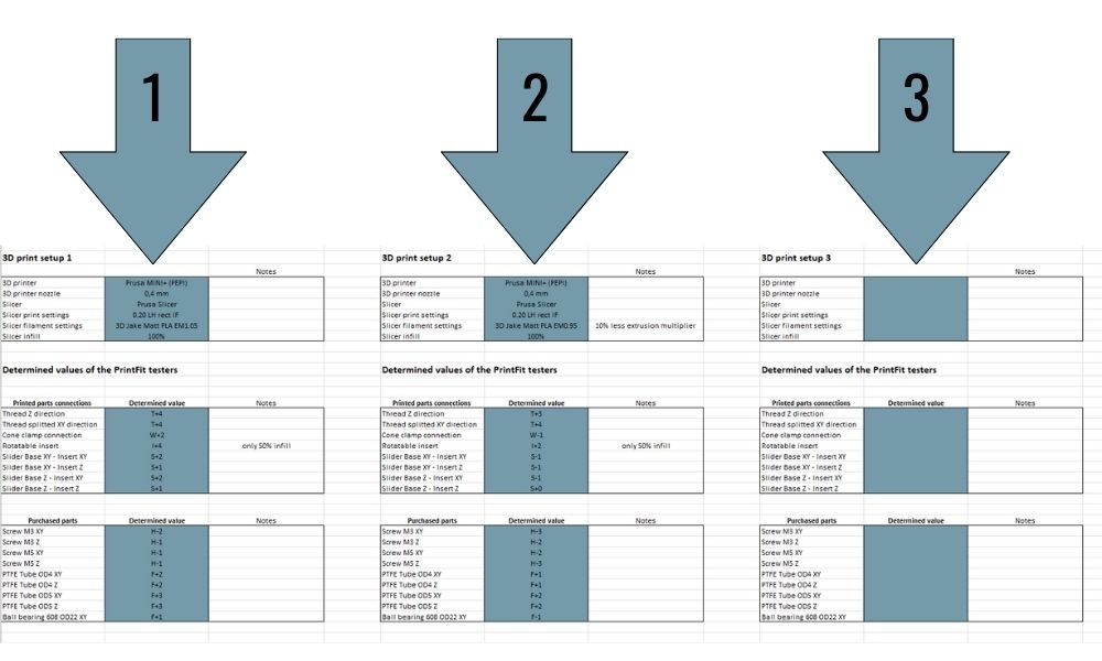
You can then simply test several setups (different nozzle diameters, infill, flow rates, printers, etc.) for each filament and enter the values.
The templates already contain input fields for the values from three different setups, of course you can copy the tables and add more.
I hope the article and the files help you with your project and take you to the next level of 3D printing 😉
Please comment and write me if you have any other ideas for the PrintFit system or if you have any questions. Happy printing!
Hello all!
This is a very nice tutorial, and I have the Box ne too!
As I am starting, the Rotatable insert piece is stuck in all positions, and the gear ones only fit in last 2.
Can you provide the configs in Cura for that? Maybe small lines or anything.
Using PLA in default configs and a Ender 3 V3 SE.
Thanks!
Hello!
Thank you very much! Could be that it is the classical elephant foot effect and your printer is melting together all the parts at the first layers. Or in case of the printed nut making the thread at the bottom very small –> Could you please check the underside of the printed parts if the turnable inserts are melted together there? Or in case of the nut, try to screw it on upside down (with the T marking facing the threads).
If this is the case, check the steps to avoid the elephant foot effect in the linked article.
Hope I could help, best regards Marian