

Here you will find the instructions to build a filament dry box that is much more than just an airtight storage box. Everybody who prints knows following situation: the filament spools are packed airtight in plastic bags and distributed throughout the room and every change of the filament on the 3D printer is a complicated, time-consuming procedure. Then the filament spool stays on the 3D printer far too long because it was forgotten to pack the spool airtight again. As a result, the filament draws moisture and becomes dusty, both of which are bad for the quality of the next 3D prints.
The DIY filament box solves exactly this problem, because the filament spools stored in the self-made filament dry box remain airtight and dust-free – even if they are currently used to 3D print something. Once built, up to 6 filament spools fit inside and you no longer have to worry about filament storage.
New updated Version 3! There are many innovations and useful features in the new version of the filament dry box:
- PrintFit system for precisely fitting connections is introduced
- Wide pulleys for filament spool storage
- Use low-cost IKEA Samla boxes that you can make airtight in just a few steps
- Quick-lock nuts for fixing the pulleys
- Labels to identify loaded filament material
- Completely new, improved silica gel (desiccant) system with fewer purchased parts
The article contains affiliate links / advertising links, these are marked with an asterisk (*). If you make a purchase through these links, I may receive a commission at no additional cost to you.
Why should I build a filament dry box?
3D printing filaments absorb water over time, which leads to ugly prints and printing errors. That is why it is important to keep your filament spools airtight, ideally with the addition of a desiccant (silica gel). With these instructions you can convert an airtight storage box so that you can print directly from it. Save yourself the annoying unpacking and packing of the filament spools. With a few simple purchased parts and the 3D print files of the DIY filament dry box you get the optimal addition to your 3D printer.
Advantages of the filament dry box
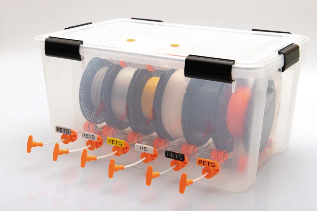
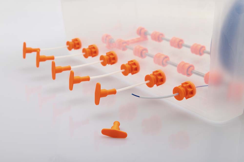
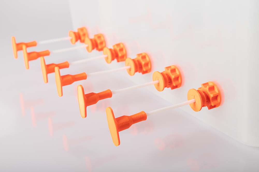
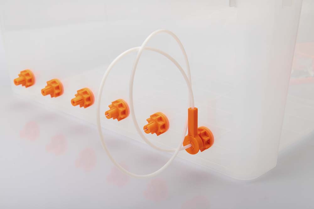
The great advantage of the filament box over other solutions is the simultaneous storage and readiness for printing with up to 6 filament spools. Simply pull the sealing plug off the PTFE tube, pull out the filament and feed it to your 3D printer. Printing with dry and dust-free filament has never been easier.
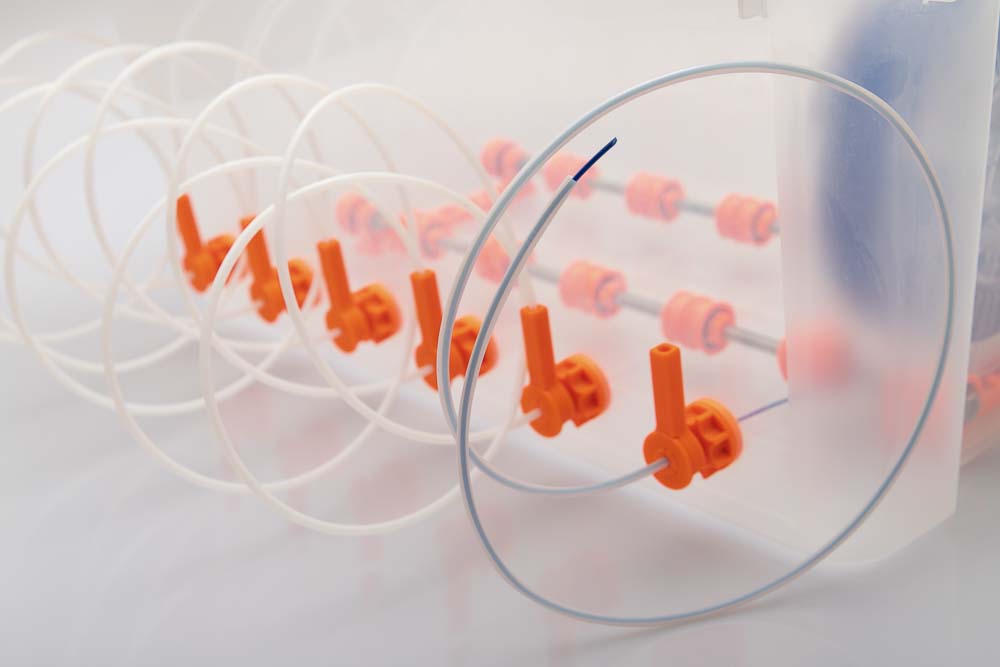
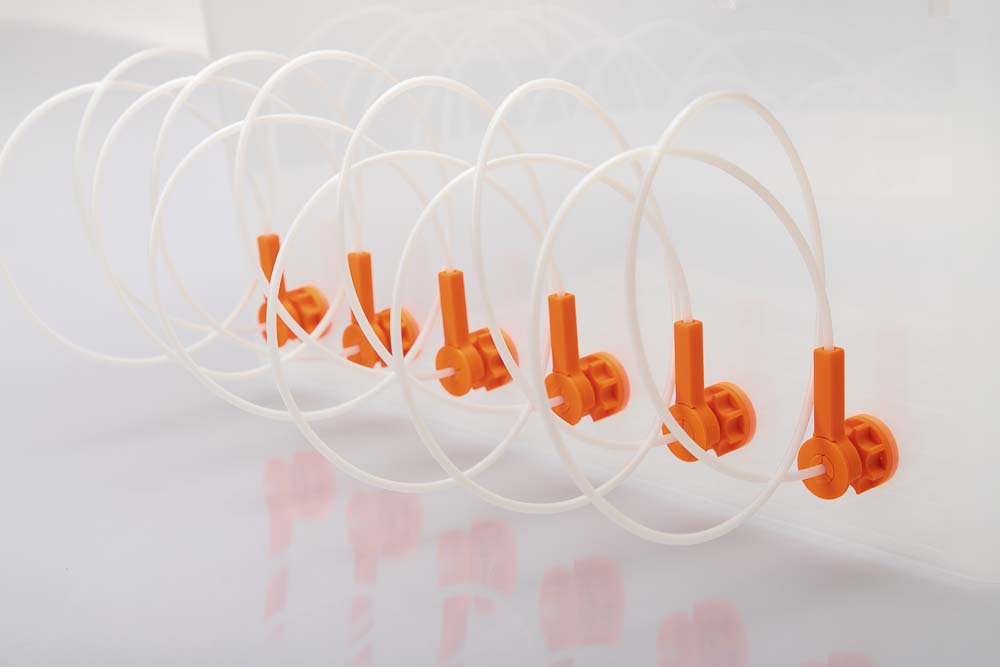
In addition to the support of 1.75 mm and 2.85 mm filament, two different variants are available for sealing the PTFE tubes. This means that long filament guides – right up to the printer – can be rolled up and stored neatly and beautifully.
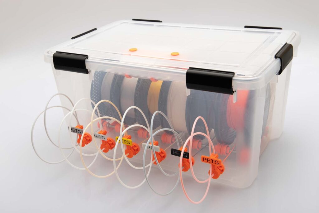
In principle, it is only a matter of preventing “spaghetti” with long PTFE tubes. The advantage of long filament guides, as shown in variant B, is that almost no excess filament has to be shortened when changing filaments, without laborious manual rolling of the filament.
- Variant A: Simple plug to seal the tubes.
- Variant B: For the sake of order, a long PFTE tube (e.g. up to your 3D printer) can be rolled up and inserted into the plug that is attached at the box.
Regardless of which plug solution is used, there is a reservoir in both where 1 – 2 cm of filament protrudes from the PTFE tube, see the cross-sections through the two variants below. The filament is colored pale green, the PTFE tube in blue.
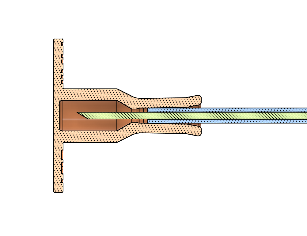
After removing the 3D printed stubble from the PTFE tube, there is always a 1 to 2 cm long piece of filament. This can then simply be pulled out and fed to the 3D printer.
Single pulley or wide pulley for filament storage?
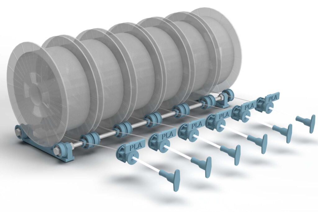
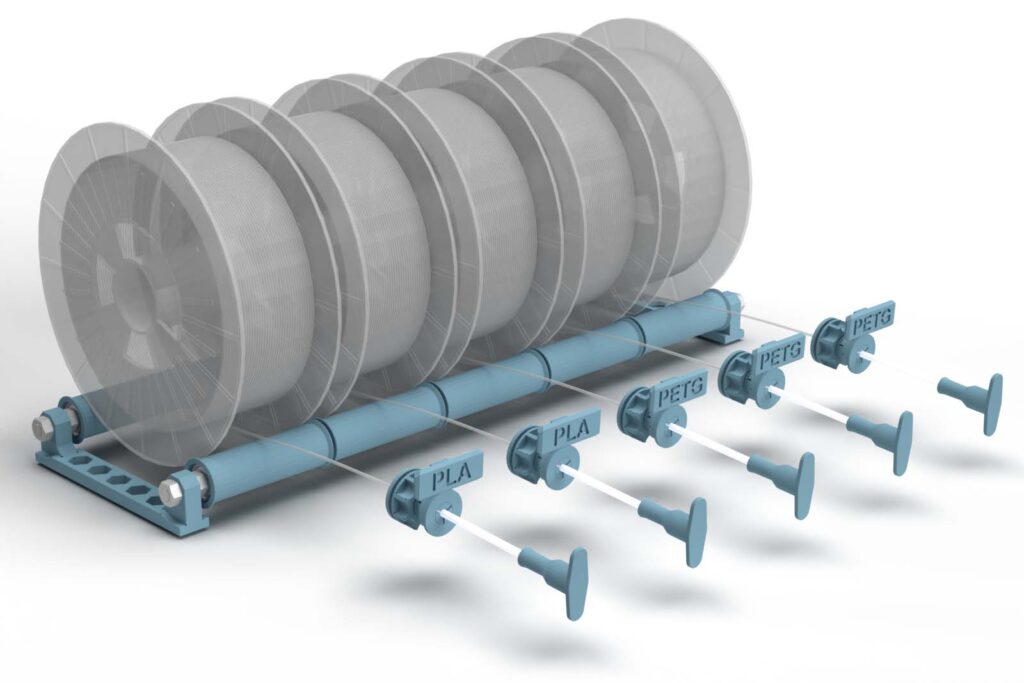
Another innovation in the third version is the ability to print wide rolls for filament storage. This means that each filament spool stands on only two wide rolls.
This version has the advantage that the position of the individual pulleys does not have to be adjusted when a spool with a different spool width is inserted.
A disadvantage of the wide rolls is that the space in the dry box cannot be used optimally and the maximum spool width is already determined when the box is built.
Here you can decide for yourself which version is best suited for your own 3D printer setup.
PrintFit system for optimal fit of connections
In addition to the new 3D print parts, the self-developed PrintFit System is now included.
The 3D print files for critical 3D printed parts such as nuts and bushings for tubes are available in five different sizes. If a connection doesn’t fit, a part can be printed with a larger or smaller gap.
Optionally, small PrintFit testers can also be printed in advance to determine the optimal gaps between 3D printed parts or with purchased parts. The testers are included in the project’s 3D printing templates. You can find more information about this in the article about the PrintFit System.
Use low-cost IKEA Samla Boxes
The new version includes all 3D print files to modify inexpensive 6 or 12 gallon (22 or 45 liter) IKEA Samla boxes to make them airtight. All you have to do is glue a sealing tape into the lid and 3D print some fasteners.
The Ikea Samla boxes are not only low-cost, but also simple and easily available everywhere. To make the boxes airtight, you need to make a few simple adjustments and print some fasteners. You can find the step by step instructions here:
Build the filament box tailored to your needs
Whether with single pulleys or wide pulleys, for five or six filament spools, with long or short PTFE tubes, with or without material labels – build the box exactly as you need it! All files are included and you can build any version you want.
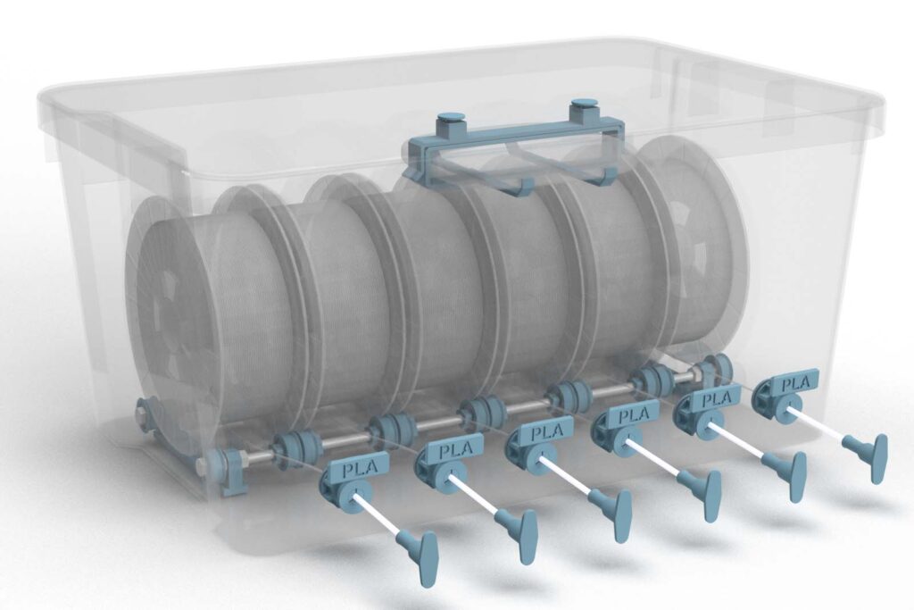
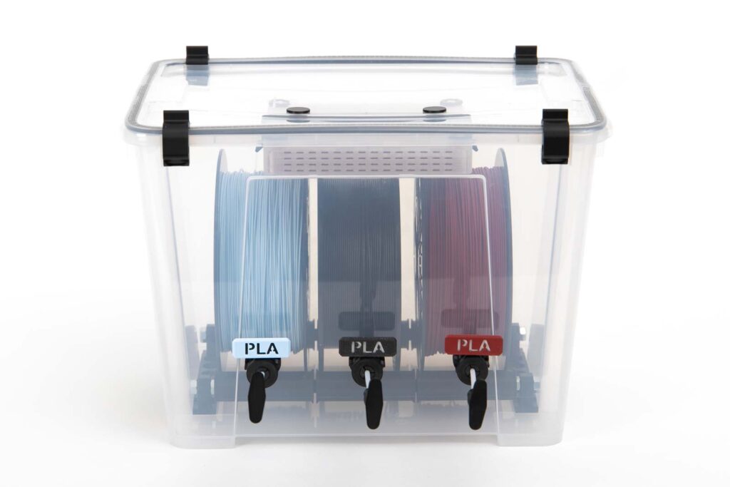
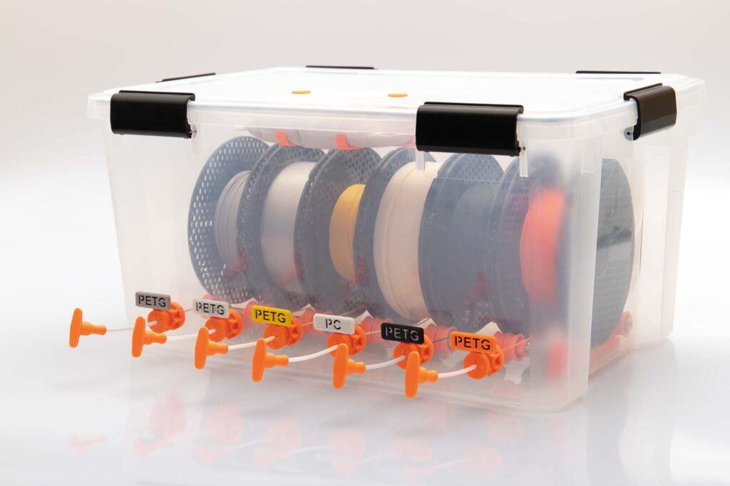
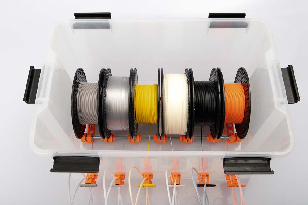
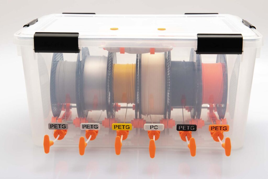
Filament box with 6 filament spools on single pulleys, the short filament tubes (version A) and a silica gel bag on the lid.
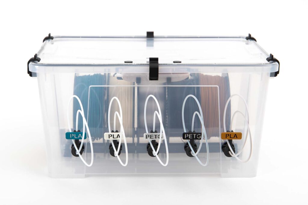
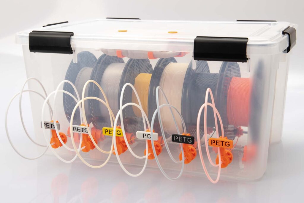
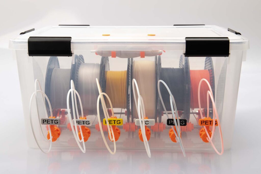
Filament box with 6 filament spools on single pulleys, the long filament tubes (version B) and a silica gel box on the lid.
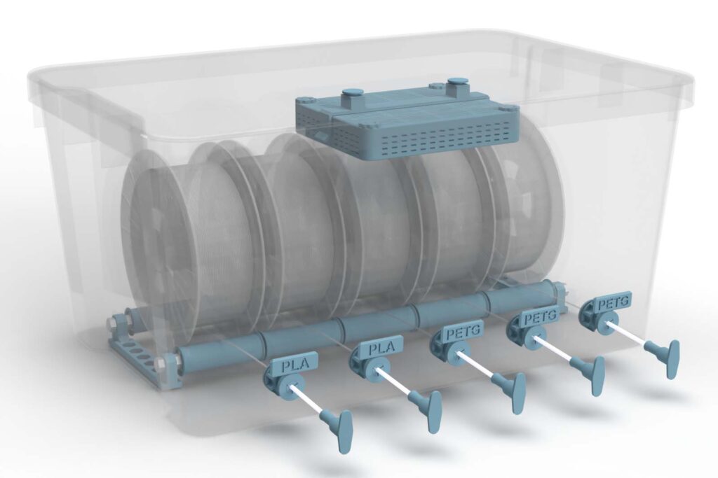
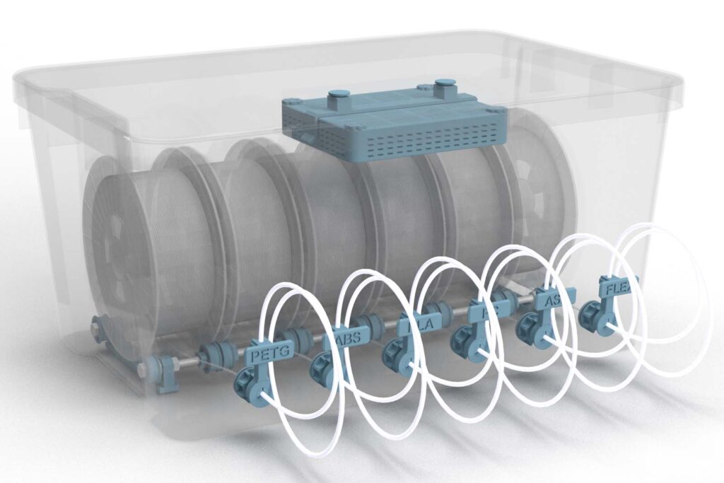
Filament box with 5 filament spools on wide pulleys, the short filament tubes (version A) and a silica gel box on the lid.
Once you have bought the 3D print files, you can of course rebuild your boxes again and again by simply printing and assembling the new parts. This means you can adjust your 3D printing setup in no time.
Do you want to use loose dry granules instead of silica gel bags? Then get the 3D print files for the Silica Gel Box addon for 0 EUR. The 3D printed box fits exactly into the clip that is also used for the silica gel bag.
3D print files of the DIY silica gel box
Instructions to build the DIY silica gel box
The instructions are divided into individual steps. To provide a short overview the safety instructions, the required 3D printing parts, purchased parts and tools are summarized right at the beginning.
3D printed parts
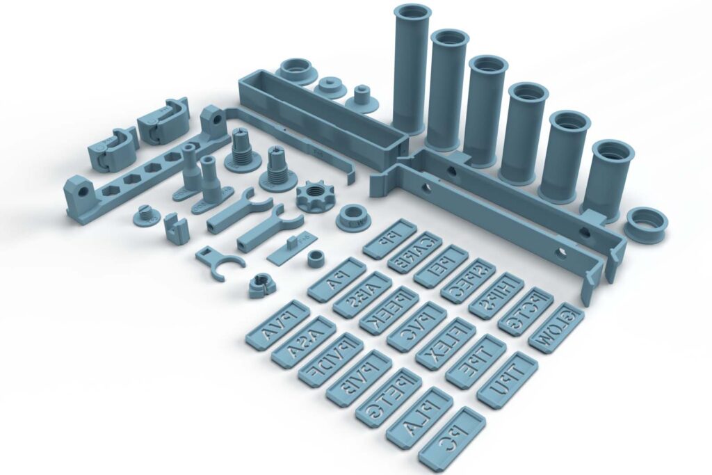
These are purely digital products, you get all the files you need to print the parts yourself in a ZIP folder. It contains the STL files for all required components and variants, as well as additional accessories.
- 006100_Rod_Mount
- 006200_Pulley_F## (PrintFit)
- 006220_Pulley_Wide_L##_F## (PrintFit)
- 006300_Spacer
- 006400_Quick_Lock_Nut_T## (PrintFit)
- 006500_Filament_Outlet_OD4_F## (PrintFit)
- 006600_Filament_Outlet_OD5_F## (PrintFit)
- 006700_Nut_T## (PrintFit)
- 006800_Clamping_Ring_W## (PrintFit)
- 006900_Plug_Variant_A_OD4_F## (PrintFit)
- 007000_Plug_Variant_A_OD5_F## (PrintFit)
- 007100_Plug_Variant_B_OD4_F## (PrintFit)
- 007200_Plug_Variant_B_OD5_F## (PrintFit)
- 007300_Silica_Gel_Clip_H3
- 007300_Silica_Gel_Clip_H12
- 007400_Silica_Gel_Screw_T## (PrintFit)
- 007500_Silica_Gel_Bag_Bracket
- 007600_Silica_Gel_Bag_Side_Support_F## (PrintFit)
- 008200_Clip_Variant_A
- 008300_Clip_Variant_B
- 008400_Contrast_Plate_F## (PrintFit)
- 008500_ABS_Sign
- 008600_ASA_Sign
- 008700_CARB_Sign
- 008800_FLEX_Sign
- 008900_GLOW_Sign
- 009000_HIPS_Sign
- 009100_PA_Sign
- 009200_PC_Sign
- 009300_PCTG_Sign
- 009400_PEEK_Sign
- 009500_PEI_Sign
- 009600_PETG_Sign
- 009700_PLA_Sign
- 009800_PP_Sign
- 009900_PVA_Sign
- 010000_PVB_Sign
- 010100_PVC_Sign
- 010200_PVDF_Sign
- 010300_SPEC_Sign
- 010400_TPE_Sign
- 010500_TPU_Sign
- 010900_Samla_Fastener_22L_I## (PrintFit)
- 011000_Samla_Fastener_45L_I## (PrintFit)
- 000400_Tool_Bearing_Press_In
- 000500_Tool_Bearing_Press_Out
- 000600_Tool_Bearing_Press_Counter
The largest 3D printed part of this project (007300_Silica_Gel_Clip_H12) requires a base area (X, Y) of 187 x 40 mm, the highest part (006220_Pulley_Wide_L100) is 105 mm high (Z). By turning the clip in the slicer by 45°, a smaller print plate is sufficient. Any 3D printer with a build volume (X, Y, Z) of at least 160 x 160 x 110 mm is suitable for this project.
3D print settings
For the 006100_Rod_Mount:
- Layer height 0.2 mm and 20% infill (rectangular)
For all other parts:
- Layer height 0.2 mm and 100% infill (rectangular)
The following settings have proven themselves for the used PETG*:
- Nozzle temperature: 250°C (First layer: 240°C)
- Bed temperature: 90°C (First layer: 85°C)
- Perimeter speed: 45 mm/s (First layer: 10 mm/s)
- External and short perimeter speed: 25 mm/s (First layer: 10 mm/s)
- Infill speed: 80 mm/s (First layer: 10 mm/s)
- Top solid infill speed: 40 mm/s
Used 3D printing filament and 3D printer
For this instruction mostly Prusament PETG Prusa Orange* Filament was printed on a Prusa i3 MK3s* 3D printer with a standard 0.4 mm nozzle.
The calculated values are based on a filament box for 6 filament spools with single pulleys, variant A plugs, a silica gel bag holder and with material labels.
Approximately 345 g PETG filament is needed for all required parts of one filament box. At a price per kilo of EUR 29.90, this is around EUR 10.34 in material costs for one filament box.
The total 3D printing time for all required components is approx. 38 hours. To calculate the total 3D printing time, all printing times are added up, whereby the total number of pieces of a component is always printed at once.
Because of the higher stability and the low warpage, I recommend PETG filament. The parts could be also be printed with ABS or ASA, but these place higher demands on the 3D printer and operator. The widespread PLA is not recommended because technically more demanding parts are not stable enough due to the more brittle nature and the lower layer adhesion of this material. In particular, the clamping jaws of the Filament_Outlet can fail, see the safety information.

It is essential to print the Filament_Outlets with 100% infill and a mechanically resilient material (PETG, ABS, ASA, etc.). Tests of an external tester have shown that these components, printed with PLA, can break when they are clamped or after a while after assembly.
Bill of materials: Needed purchased parts for the filament dry box
- 1 pc 62.8 Qt air-tight box (Amazon.com US)* (approx. 37 USD / pc) or 46.6 Qt air-tight box (Amazon.com US)* (approx. 37 USD / pc) – in this instruction the 50L air-tight box (Amazon.de DE)* is used, unfortunatly only available in Europe
- 24 pcs Ball bearings 608 (Amazon.com US)* (approx. 9 USD / 20 pcs) – Version for 6 filament spools (amount spools x4)
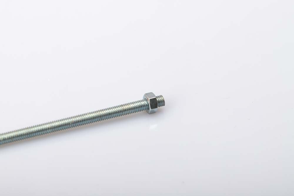
- 2 pcs 500 mm Threaded rod M8 x 1.25 (Amazon.com US)* (approx. 6.7 USD / 500 mm)
- 12 pcs Nut M8 x 1.25 DIN934 (Amazon.com US)* (approx. 6 USD / 20 pcs)
- 1-6 m PTFE tube OD4 ID3 (Amazon.com US)* (approx. 3 USD / m) – alternatives possible
- 1 pc Silica gel bag (Amazon.com US)* approx. 15 x 17 x 3 cm (approx. 11.5 USD) – alternatives possible
Instead of the linked airtight box, the inexpensive Ikea Samla boxes: IKEA Samla box 12 gallon (45 liter) (about 13 USD) or IKEA Samla box 6 gallon (22 liter) (about 7 USD) can also be used. However, these must first be slightly modified, see the instructions here: Build Ikea Samla Filament Box
The dimensions of the air tight boxes from Amazon US – 62.8 Qt and 46.6 Qt – are close to the box used in this instruction (50L air-tight box (Amazon.de DE)*), but not identical. Please check your filament spool dimensions, adapt the length of the threaded rods, and the distance and amount of the filament outlets. The total costs of the purchased parts come to approx. 70 USD. For the calculation only the costs for the required parts for one filament box were added together.
Alternative purchased parts
Threaded rod, screws and nuts: They are usually much cheaper in hardware stores and can be bought there in the required number of pieces.
PTFE tubes: Besides the OD4 ID3 (outer diameter 4 mm and inner diameter 3 mm) it is also possible to build the filament box with OD4 ID2 and OD5 ID3 tubes. Use tubes with an inner diameter of 3 mm if the box is built for 2.85 mm filament. But I also recommend the ID3 tubes in variant B with long filament guides, as the friction in the ID2 tubes on longer distances is higher, especially with rough filament (matt colors). Depending on the version you are going to build more or less tube length is needed.
Silica Gel: If you already got other silica gel bags or if you prefer loose desiccant, then download the 3D print files of the DIY silica gel box. With this free addon loose silica gel granules can be used in the filament dry box.
Airtight box: Of course, other airtight boxes can also be used, but please check the dimensions to ensure that the filament spools have enough space in them. The length of the threaded rods must then be adapted to the respective width of the alternative box.
Additional parts
To check the humidity level in the box, a hygrometer (Amazon.com US)* can be bought for about 8 USD. The measuring range for the humidity starts with these hobby devices only at 10% to 20%, that means even if the measuring device shows these values and not 0% everything is fine.
Required tools
As always, a new project is the best excuse to buy new tools 😉
- Cordless screwdriver (Amazon.com US)*
- Wrench set basic (Amazon.com US)* (M8 wrench size 13 mm)
- Wood drill bit 2 mm (Amazon.com US)*
- Wood drill bit 4 mm (Amazon.com US)*
- Step drill bit (Amazon.com US)* (including 16 mm step)
- Hacksaw (Amazon.com US)* (for cutting the threaded rod)
- Metal file (Amazon.com US)* (for deburring the thread cuts)
- Marker pen (Amazon.com US)*
- Box cutter (Amazon.com US)*
- Scissors (Amazon.com US)*
- Double-sided tape (Amazon.com US)*
Wood drill bits cut best through the plastic of the box.
Instructions: Build a DIY filament box
The assembly instructions for the filament dry box are divided into 5 individual steps, which are divided into the following chapters:
- Step 1: Build the filament spool storage
- Step 2: Mount the filament outlets into the airtight box
- Step 3: Tape the filament spool storage into the filamet box
- Step 4: Attach silica gel bag holder to the lid
- Step 5: Load the finished filament box and test it
Safety Guidelines
Safety first! Read and follow the assembly instructions and the operation manual!
Read the entire assembly instructions and operating manual carefully and follow the instructions and safety warnings. If anything is unclear, simply contact support (support@3d-druck-vorlagen.de).
These instructions are only intended for persons of legal age (over 18 years old). If you lack knowledge in handling the tools or processes that occur, then it is essential to seek the help of trained persons. The preparation and assembly of the project is at your own risk.
Legend: Warnings and Symbols


General safety instructions for assembling the project
Wear protective goggles to protect your eyes during all processing steps that can produce chips (sawing, drilling).
Wear assembly gloves to protect your hands during all processing steps in which saws or knives are used. Do not wear gloves when drilling, there is a risk of being drawn into the drill.
When printing parts, sharp edges can occur (usually on the first layer), there is a risk of cuts! These edges have to be ground down in order to deburr them.
Step 1: Build the filament spool storage
It is possible to store the filament spools on single pulleys or on wide pullys. Each version has its advantages and disadvantages, which are briefly listed here.
It’s entirely up to you which version you choose. If you want to switch to the other version later, that’s no problem.
Filament storage on single pulleys
The variant with single pulleys has the advantages:
- more space in the box can be used
- can be flexibly adjusted to any spool width
and the disadvantages:
- the distance between the individual pulleys must be adjusted if the spool width is different
Filament storage on wide pulleys
The variant with wide pulleys has the advantages:
- faster when changing between spools with different spool widths
and the disadvantages:
- less space in the box can be used
- maximum spool width is limited by the choice of wide pulleys
If you notice later that the other version would be better, that’s no problem, just print out the parts you need and convert them.
Simply summarized: If the filament spools in the box are rarely or almost never changed and if you want to remain flexible, then use the single pulley version. If you often switch between spools with different spool widths, then the version with the wide pulleys is the better choice for you. When planning, it is important to focus on the widest spool you want to use.
Assembling the storage variant with single pulleys
The instructions for building the filament spool storage with single rolls can be found right here, the assembly instructions for storage with wide rolls can be found afterwards or by clicking here: Assembling the storage variant with wide pulleys
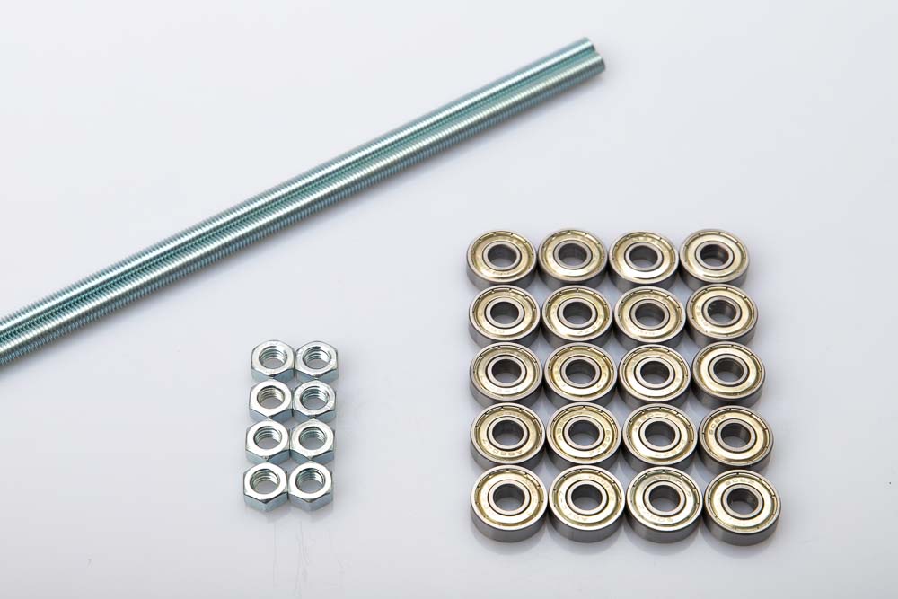
Required purchased parts
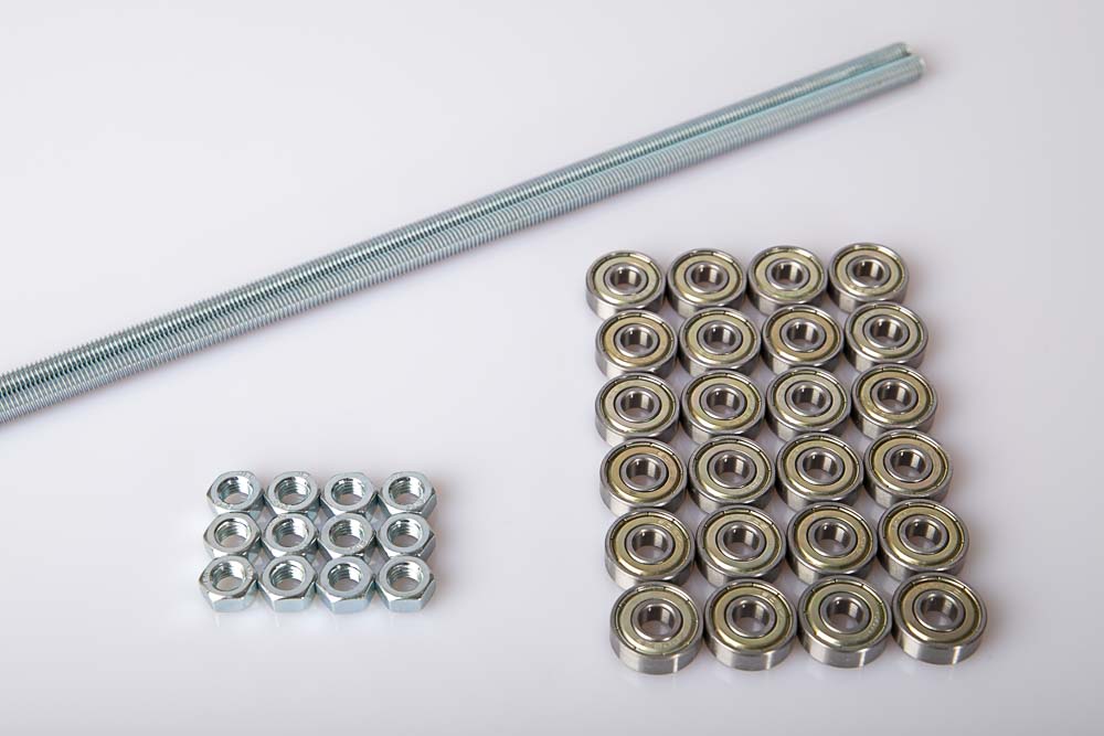
- 24 pcs Ball bearings 608
- 1 m Threaded rod M8
- 12 pcs Nuts M8 DIN934
Saw the threaded rod into two pieces of equal length with a hacksaw. Here measure the maximum possible length in the selected airtight box.
For the air tight Iris 50L box used here, saw the threaded rod into two 485 mm long pieces. For the Iris 62.8 Qt and the Iris 46.6 Qt you need to measure the maximum possible rod length at the bottom of the boxes.
Clamp the threaded rods securely before sawing, wear protective goggles and gloves when cutting.
Beware of sharp metal grades! Deburr the threaded rods with a file after sawing.
Required 3D printed parts
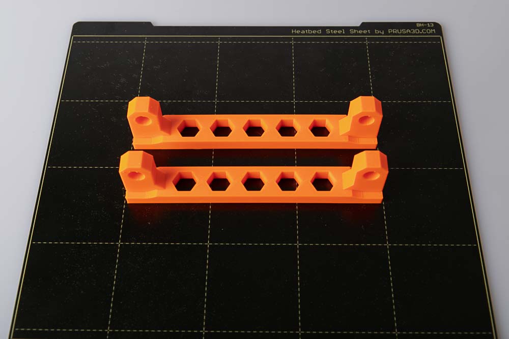
- 2 pcs 006100_Rod_Mount
Layer height 0.2 mm and 20% infill (rectangular)
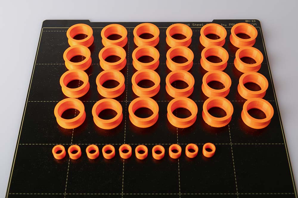
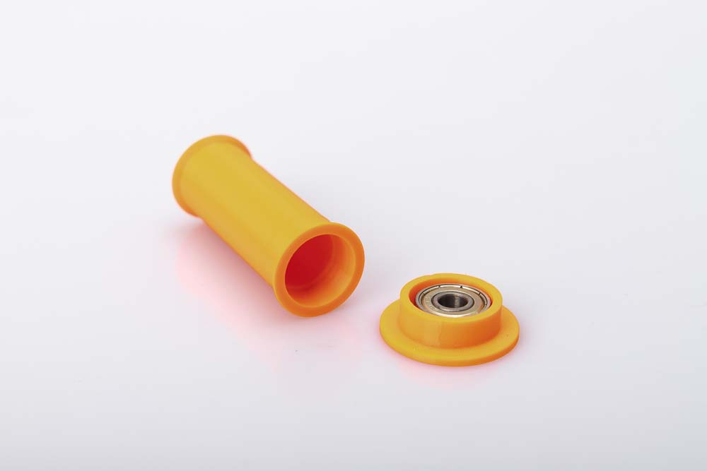
- 24 pcs 006200_Pulley_F##
- 10 pcs 006300_Spacer
Layer height 0.2 mm and 100% infill (rectangular)
The pulley is a PrintFit System part:
The standard 3D print template of the pulley is F+0. If the ball bearing cannot be pressed into this version, then print version F+1, whose recess is 0.1 mm larger. If the ball bearing is too loose in the standard version F+0, then print version F-1, which has a smaller bore.
It’s best to first print just one pulley and press in a ball bearing as a test. If this works without any problems then the remaining parts can be printed.
To press the ball bearings into the pulleys, use the tools provided in the 3D print files. This makes it much easier to press in the bearings and to press them out again if necessary.
Use the included 3D printed tools for easier assembly and disassembly of the ball bearings in the pulleys.
- 1 pc 000400_Tool_Bearing_Press_In
- 1 pc 000500_Tool_Bearing_Press_Out
- 1 pc 000600_Tool_Bearing_Press_Counter
Layer height 0.2 mm and 100% infill (rectangular)
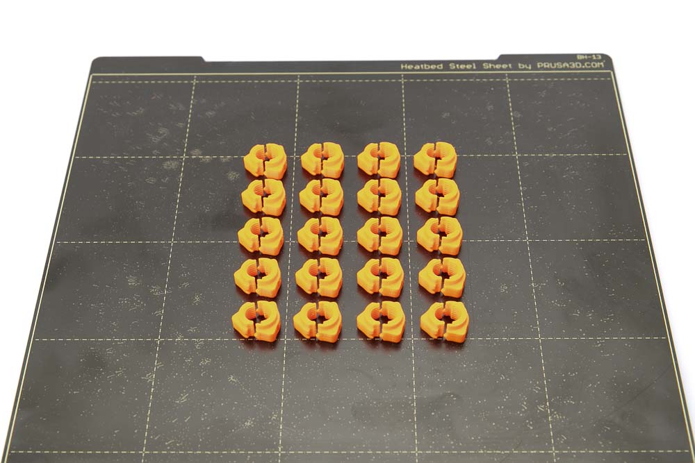
- 20 pcs 006400_Quick_Lock_Nut_T##
Layer height 0.2 mm and 100% infill (rectangular)
The quick-lock nut is a PrintFit System part:
The standard 3D printing template of the quick-lock nut is the T+4. If it is difficult or impossible to screw onto the threaded rod, then print the next larger version T+5, which creates a larger thread gap. If the standard version T+4 of the nut is too loose on the threaded rod, then print version T+3, which results in a smaller thread gap.
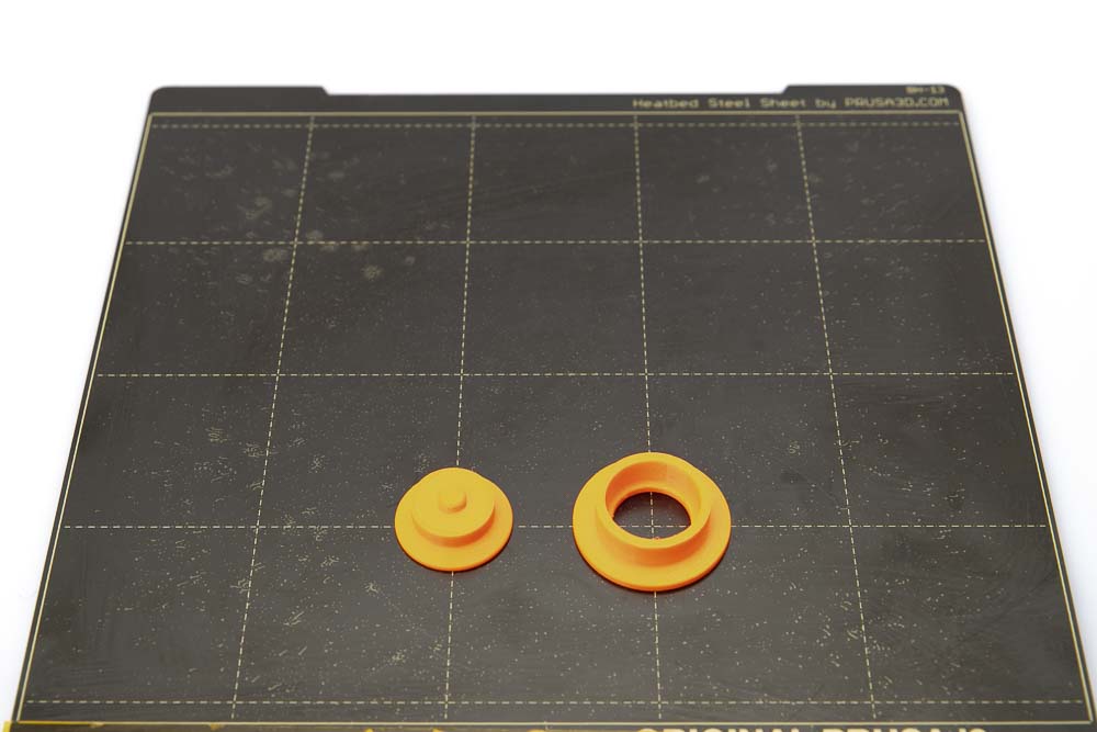
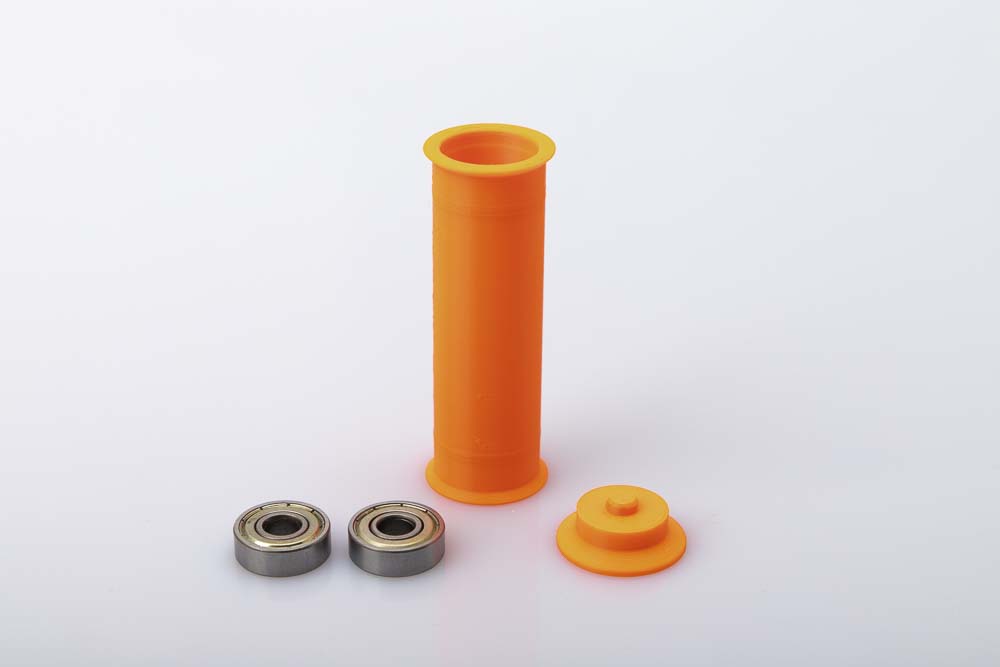
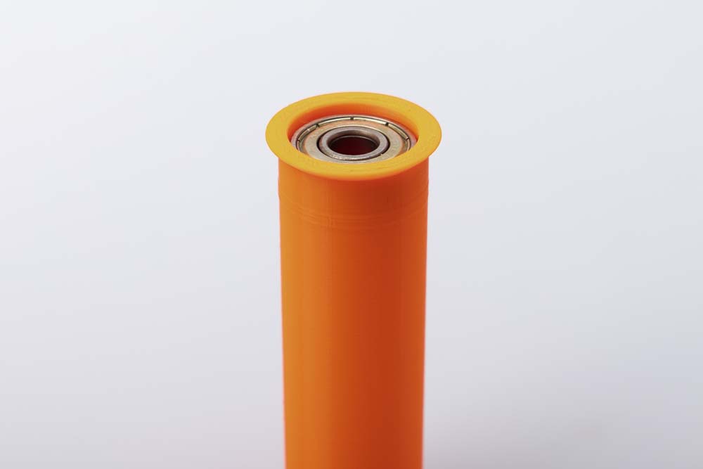
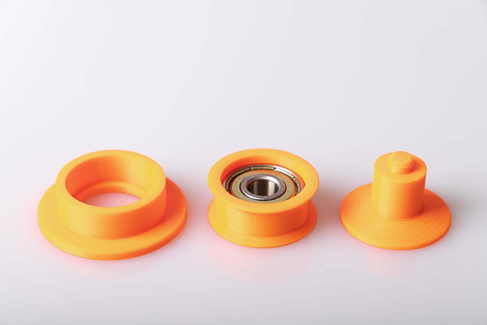
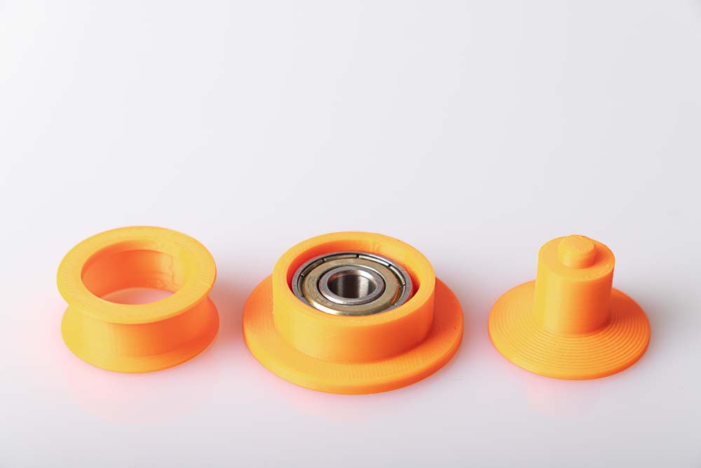
Pressing the ball bearings into the single pulleys
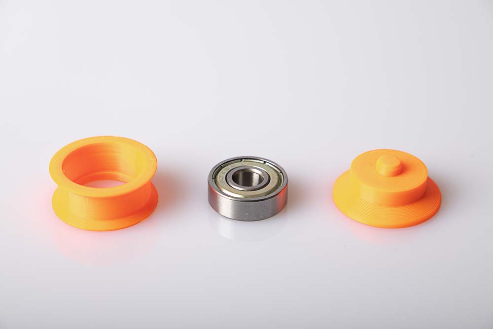
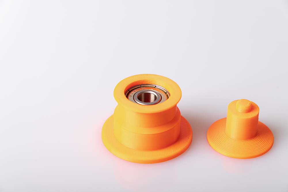
Prepare one 608 ball bearing, one 3D printed pulley and the press-in tool.
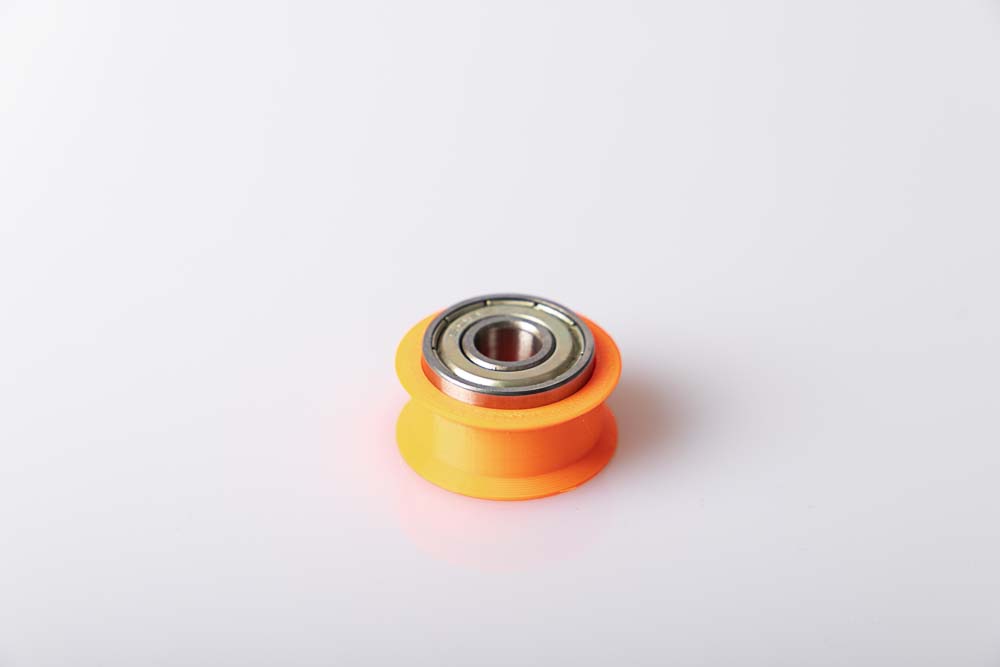
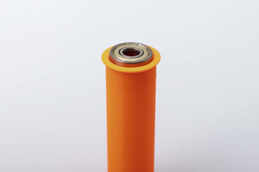
Insert the ball bearing on the side of the pulley with the larger opening.
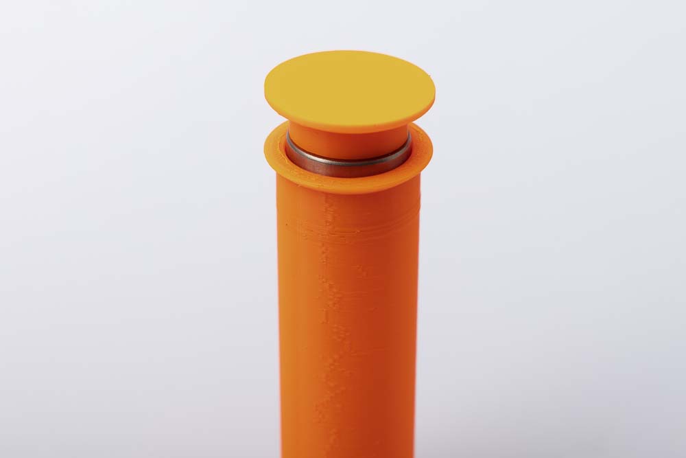
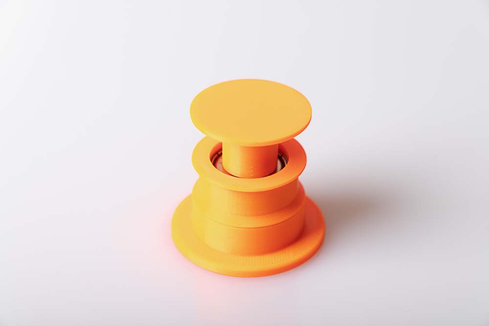
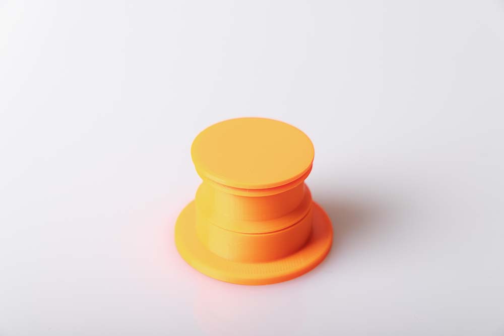
Position the press-in tool and press firmly until the ball bearing is completely pressed against the lower edge in the pulley.
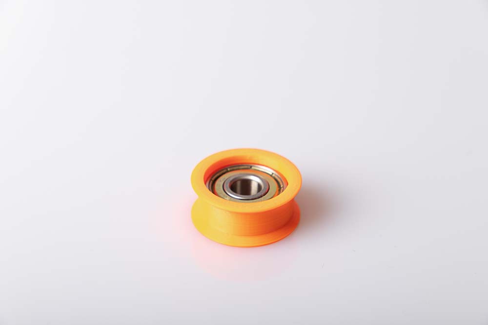
If the ball bearing has been pressed in correctly, it will sit parallel to the pulley and approx. 2 mm deep from the pulley surface.
The ball bearings must sit securely and firmly, as well as parallel and not tilted in the pulleys! Important so that the filament spools do not block later!
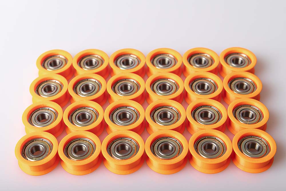
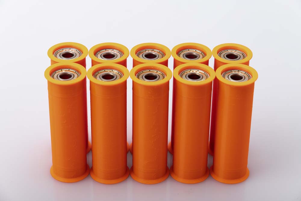
Now prepare all remaining pulleys according to the same scheme.
If something goes wrong when pressing in, or if you want to remove the ball bearing from the pulley again, the Tool_Bearing_Press_Out and Tool_Bearing_Press_Counter can be used. How this works is written down in the chapter Pressing a ball bearing out of a pulley in the appendix.
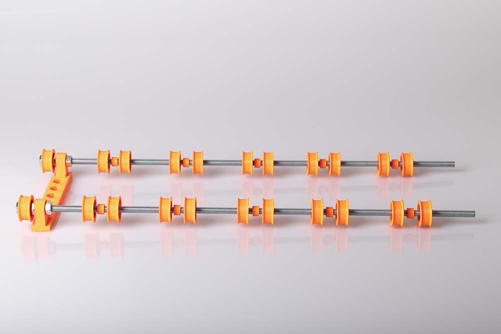
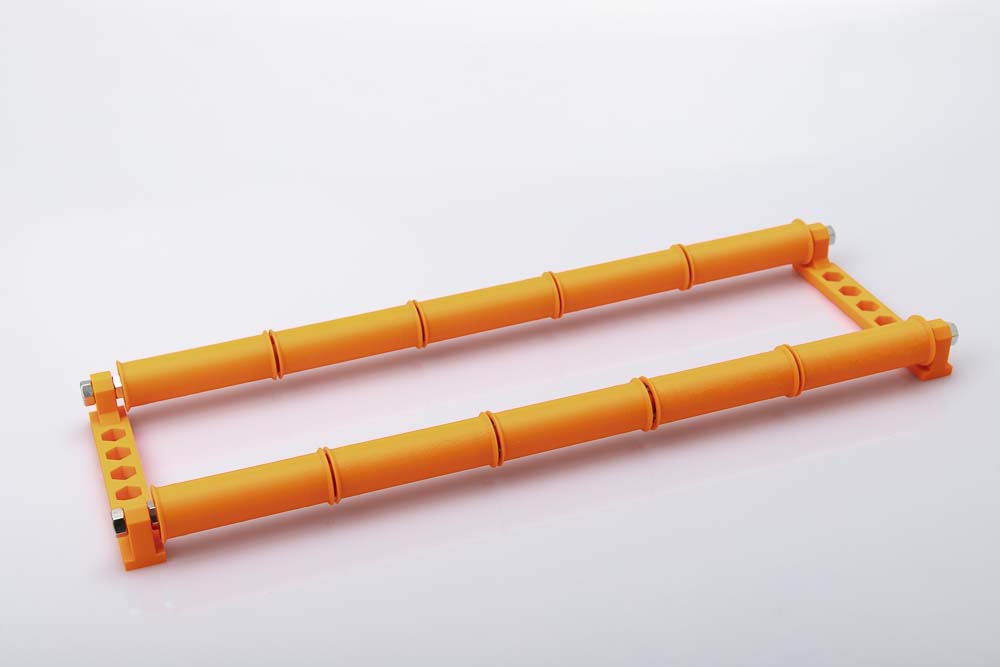
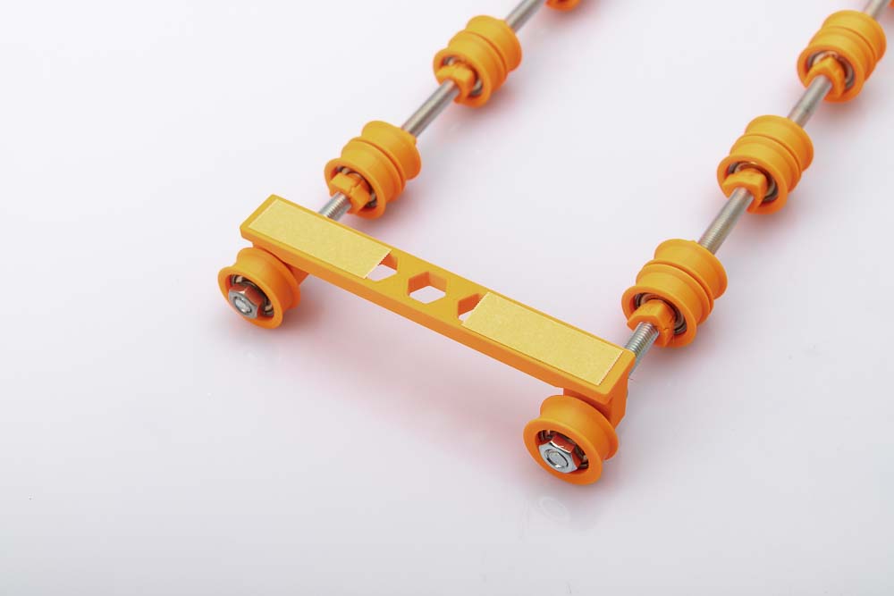
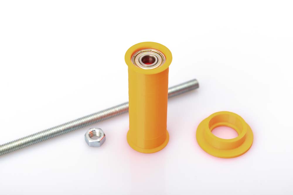
Assembling the filament spool storage with single pulleys
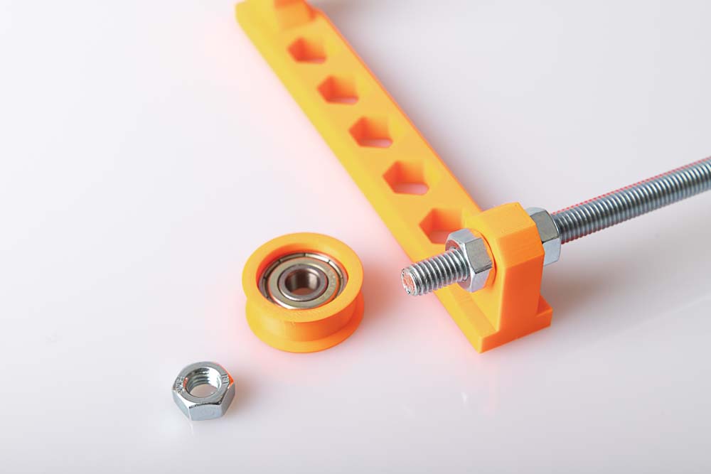
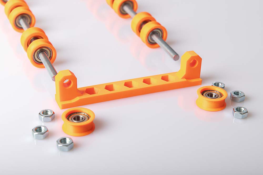
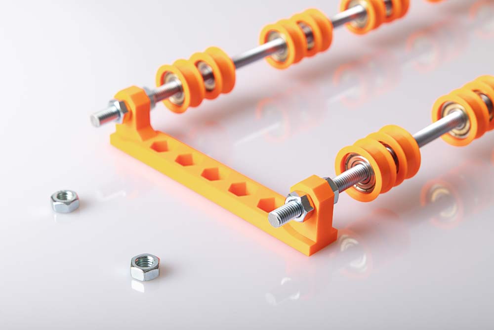
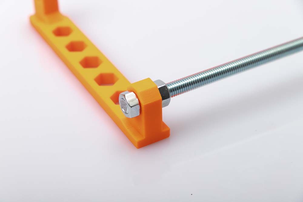
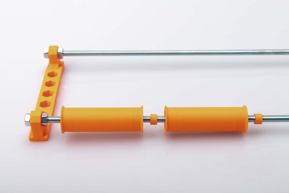
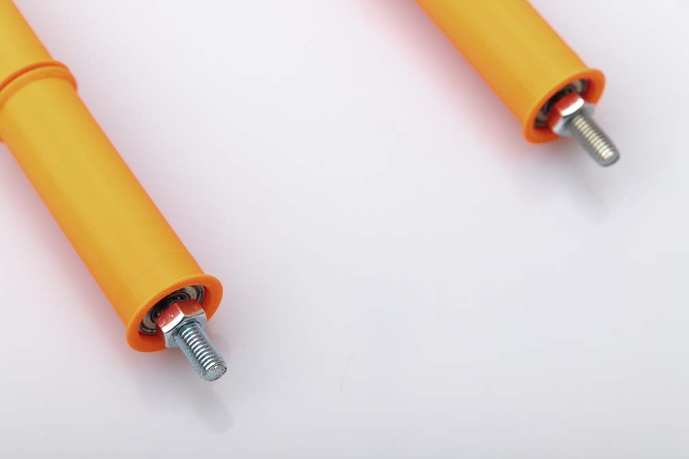
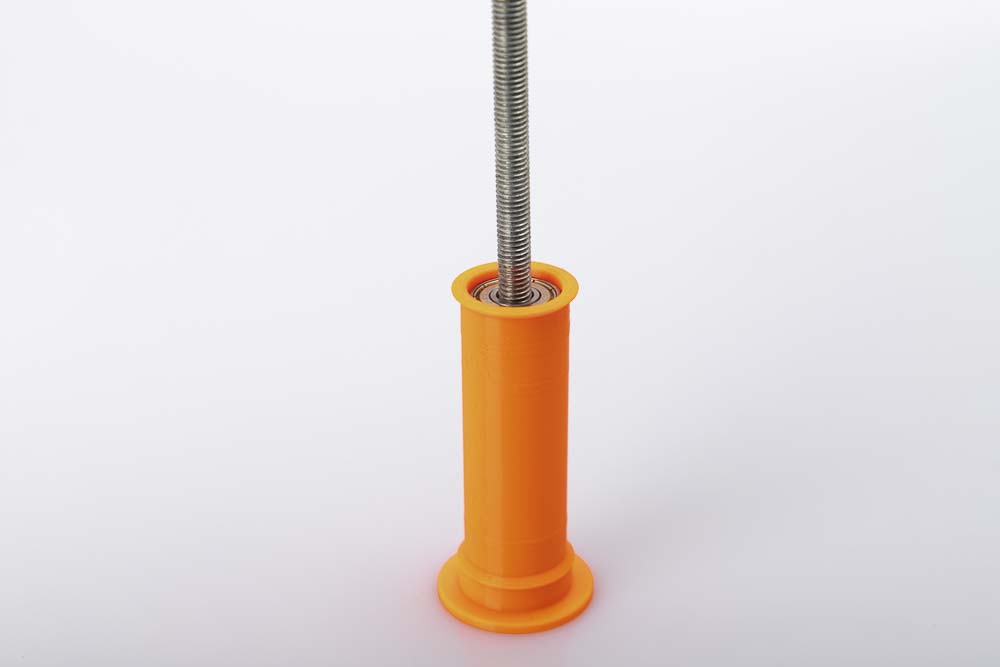
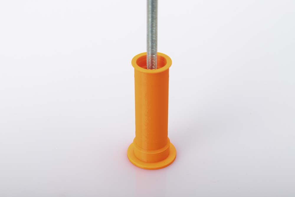
Insert one of the M8 threaded rods (485 mm) into one of the rod mounts and secure it with two M8 nuts on both sides. To do this, simply use two 13 mm open-ended wrenches. Do not tighten too much so that the 3D printed mount is not damaged. The short, free threaded rod end should still protrude approx. 13 mm beyond the nut.
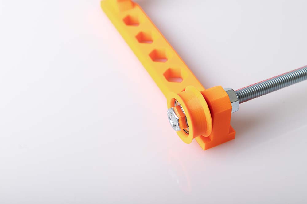
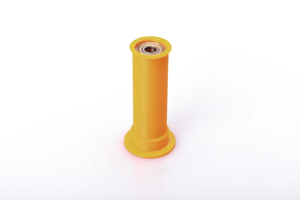
Then put on a pulley and tighten it with a third nut so that the nut and the threaded rod end are flush.

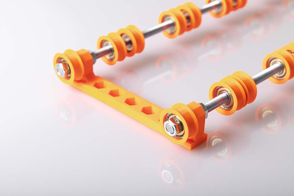
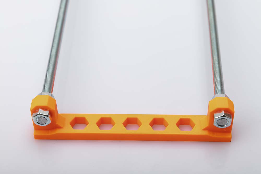
Now do the same on the second hole of the rod mount with the second threaded rod. Then it should look like the photo.
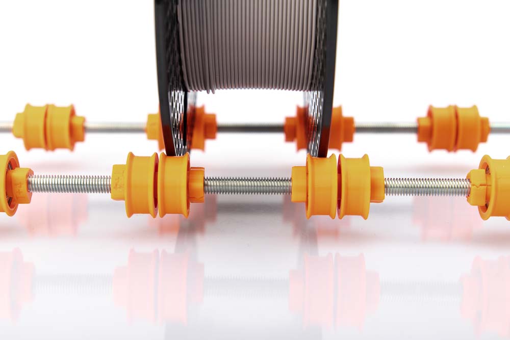
Now pull on the single pulleys and spacers on the long free side. Repeat this in following pattern: pulley – spacer – pulley, and then repeat. So thread a total of 10 pulleys and 5 spacers.
The spacers prevent that later, when two filament spools run close to each other, a stationary spool is driven from a moving one, or a stationary spool is blocking a moving one.
Check that all adjacent pulleys are separated by a spacer and that the pulleys are not hitting anywhere else.
Repeat on the second threaded rod.
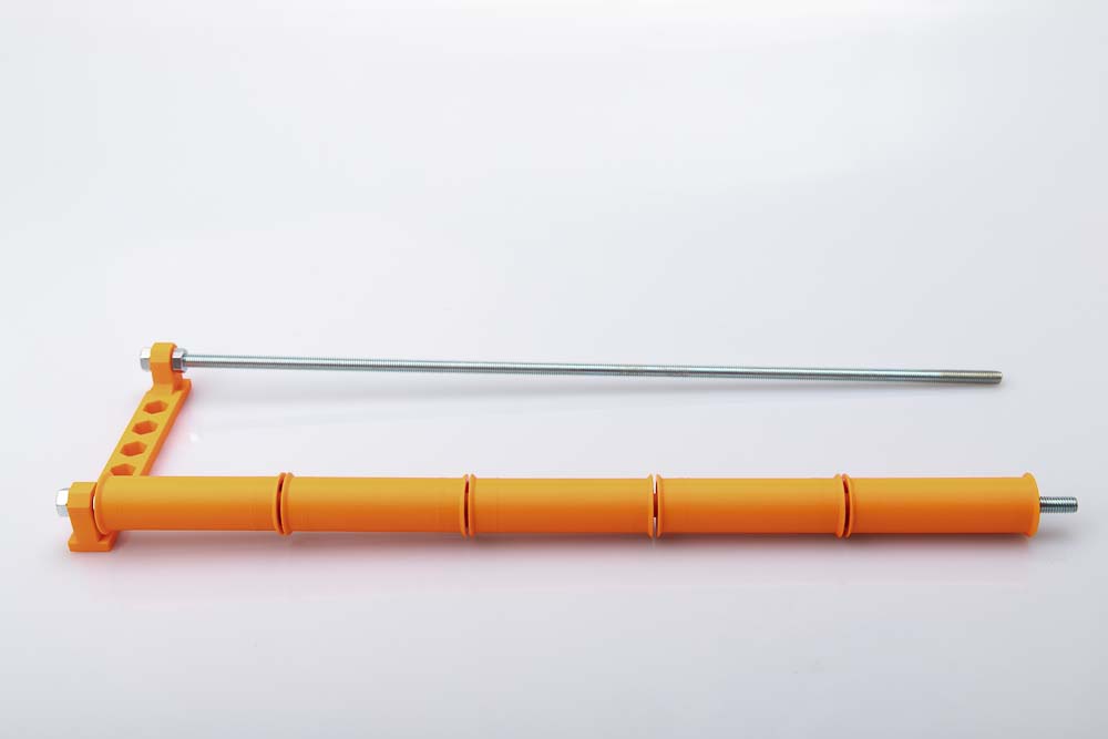
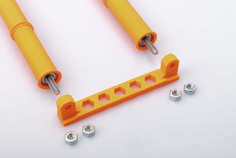
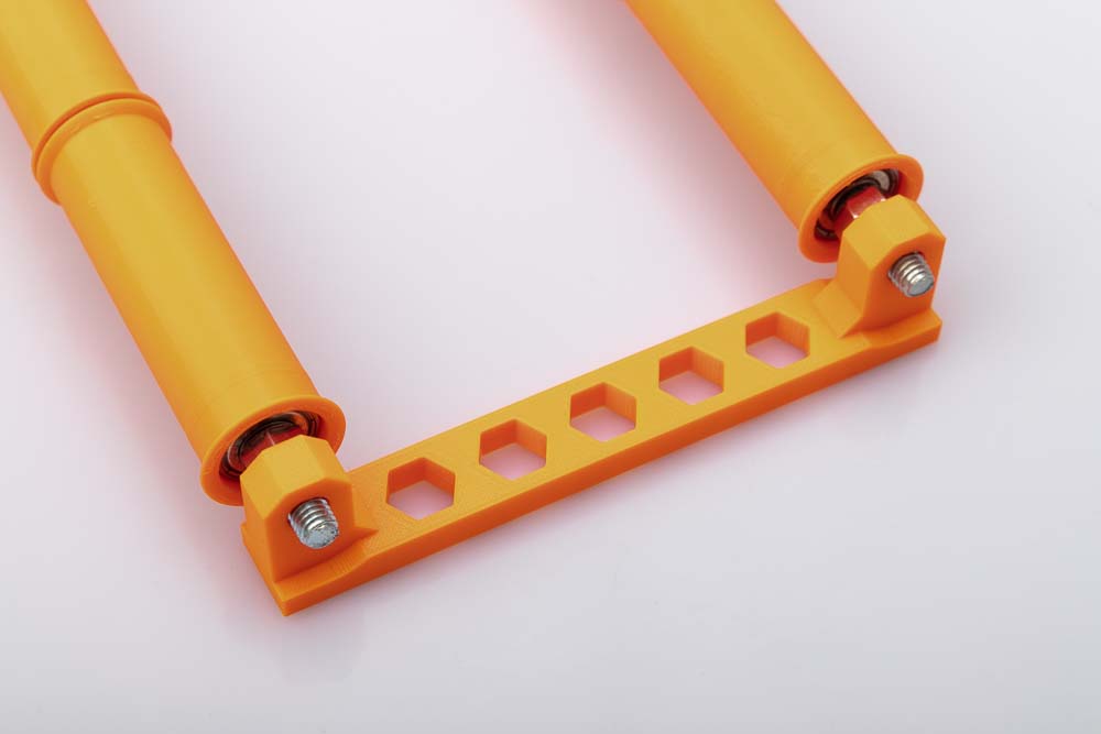
Once all the pulleys that should later run between the brackets have been drawn up, the end on the second side is prepared. In addition to the rod mount, you also need 2 pulleys and 6 M8 nuts.
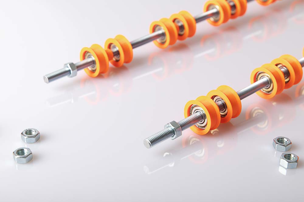
First of all, 2 nuts are screwed on, the free ends of the threaded rod should protrude approx. 30 mm.
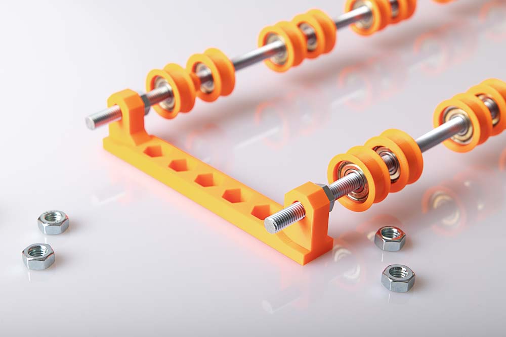
Thread the rod mount onto the two threaded rods.
Secure the rod mount with two nuts. As before: do not overtighten so that the 3D printed mount is not damaged.
Put on 2 pulleys and secure them with nuts.
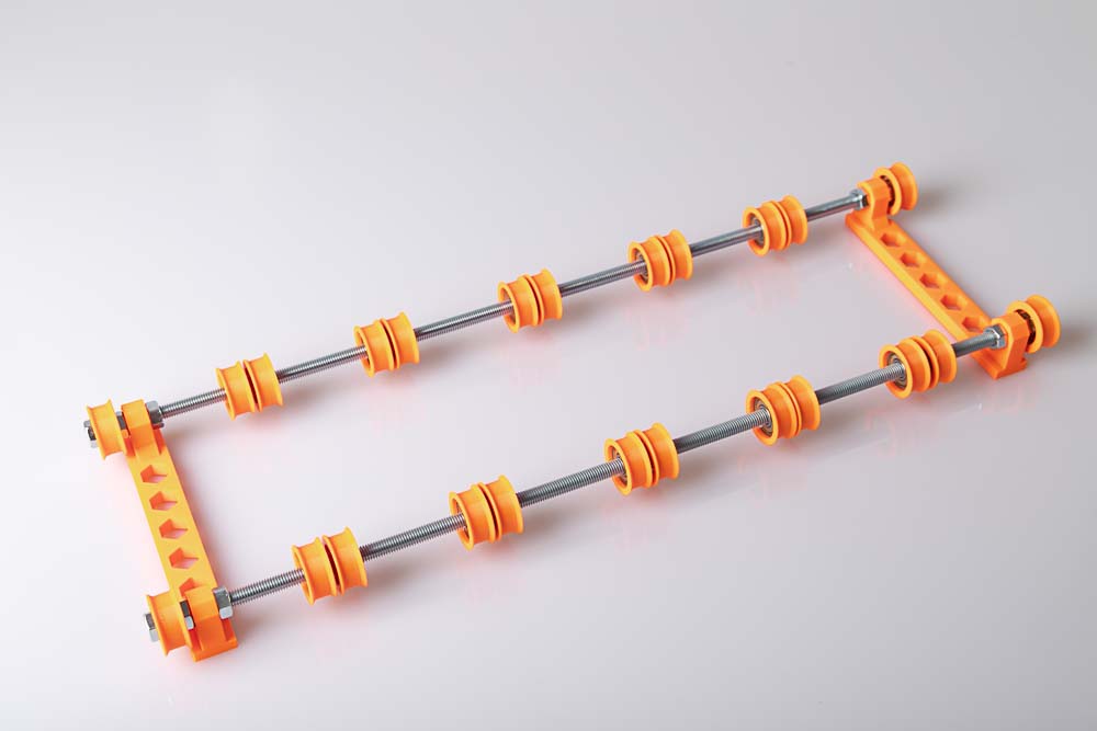
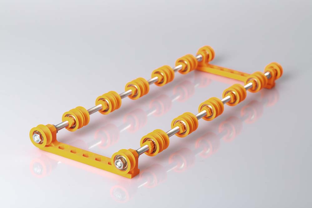
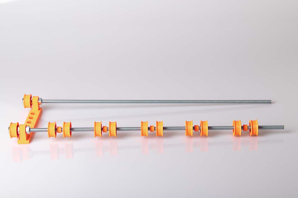
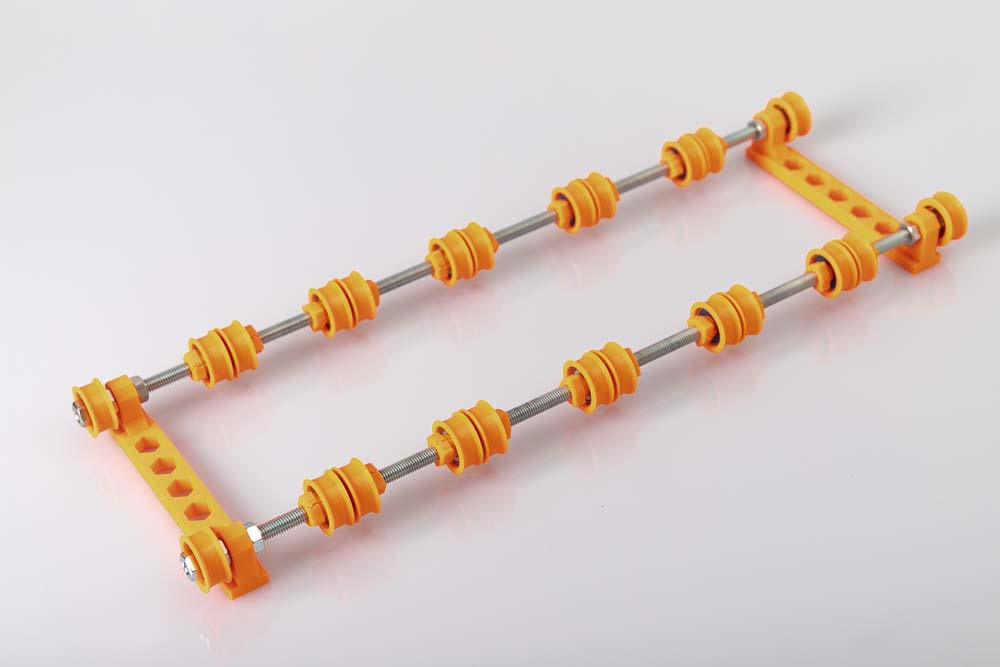
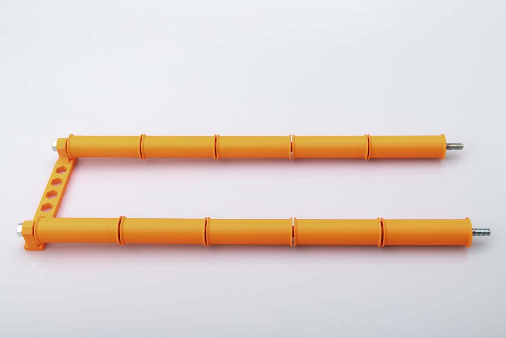
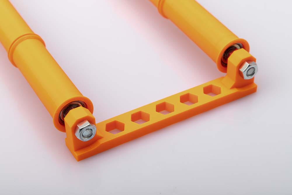
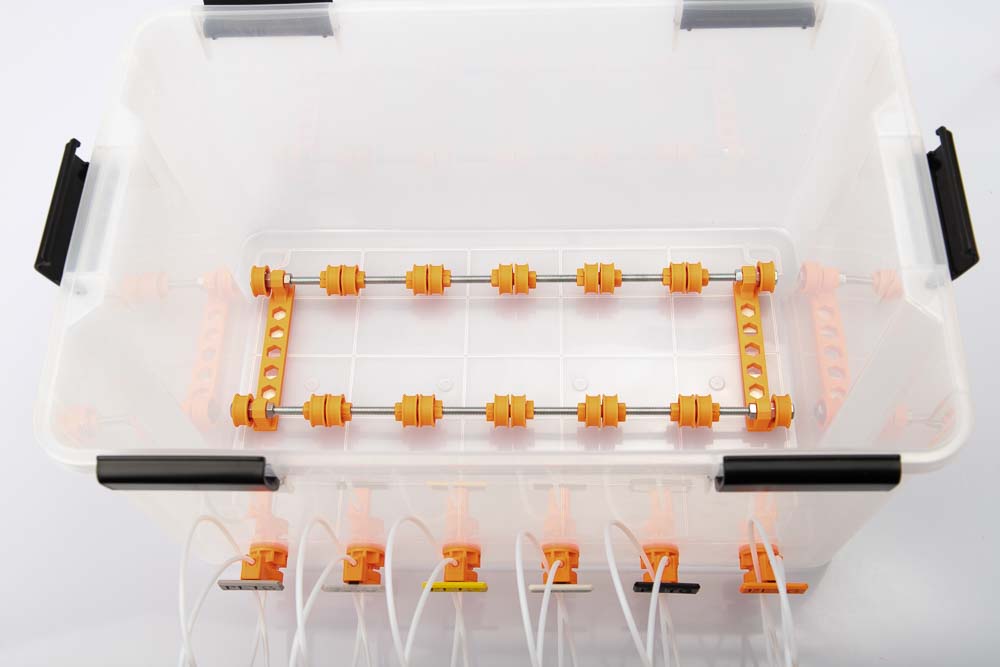
This is what the assembled filament spool storage with single pulleys should now look like.
In the last step, the pulleys are fixed in place with the quick-lock nuts.
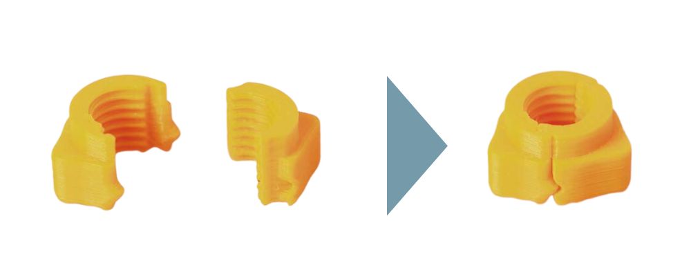
The nuts have a snap mechanism and can be easily squeezed together by hand. Make sure that the step of both parts is on the same side.
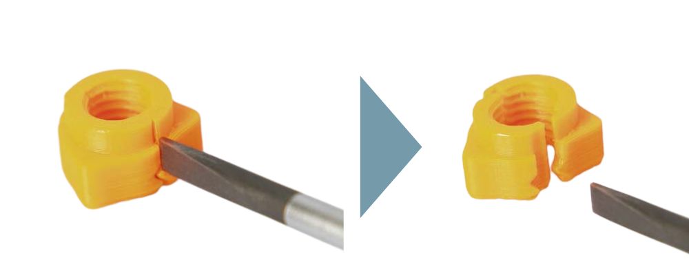
The quick-release nuts can be easily opened again with a flathead screwdriver. To do this, insert a screwdriver into the longitudinal gap of the nut and turn it slightly.
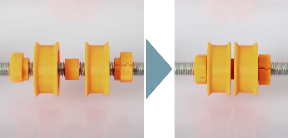
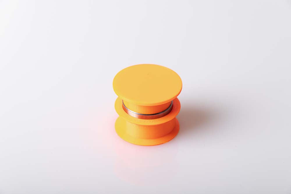
If you want to fix a pair of pulleys in a certain position, simply clip on two quick-lock nuts to the left and right of it. A single pulley, a spacer and another single pulley should then sit between the nuts. The short step on the nuts must point towards the ball bearings. Then fix the pulleys between the nuts by screw them. There must be a spacer between the two pulleys.
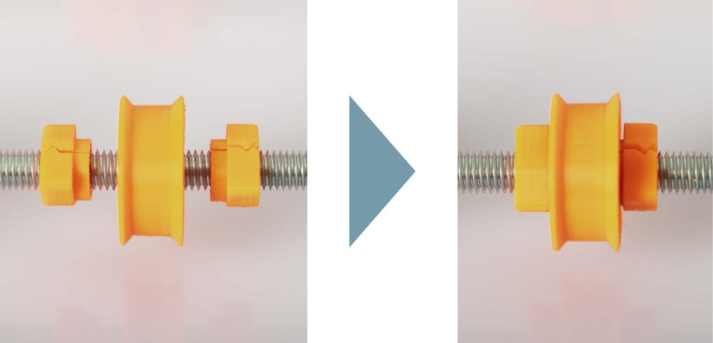
If you only want to fix a single pulley, simply clip on two nuts to the left and right of it and then fix the pulley by tightening the quick-lock nuts.
Congratulations, the filament spool storage is ready. Time for a beer!
Assembling the storage variant with wide pulleys
This are the instructions for building the filament spool storage with wide pulleys, the assembly instructions for the storage with single pulleys can be found above, or here: Assembling the storage variant with single pulleys
Required purchased parts
- 20 pcs Ball bearings 608
- 1 m Threaded rod M8
- 8 pcs Nuts M8 DIN934
For the variant with the wide pulleys, the threaded rod is sawn into two pieces of equal length with a hacksaw.
The calculation of the threaded rod length depends on the space available in the selected airtight box and the selected number and length of the wide pulleys. See the calculation formula below.
Clamp the threaded rods securely before sawing, wear protective goggles and gloves when cutting.
Beware of sharp metal grades! Deburr the threaded rods with a file after sawing.
Calculating the rod length
In this version, the spool holder can be built with wide pulleys of different widths. Of course, all STL files are included in the 3D print files.

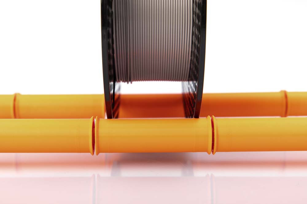
The wide pulleys are available in 6 different widths from 50 to 100 mm running surface in 10 mm increments.
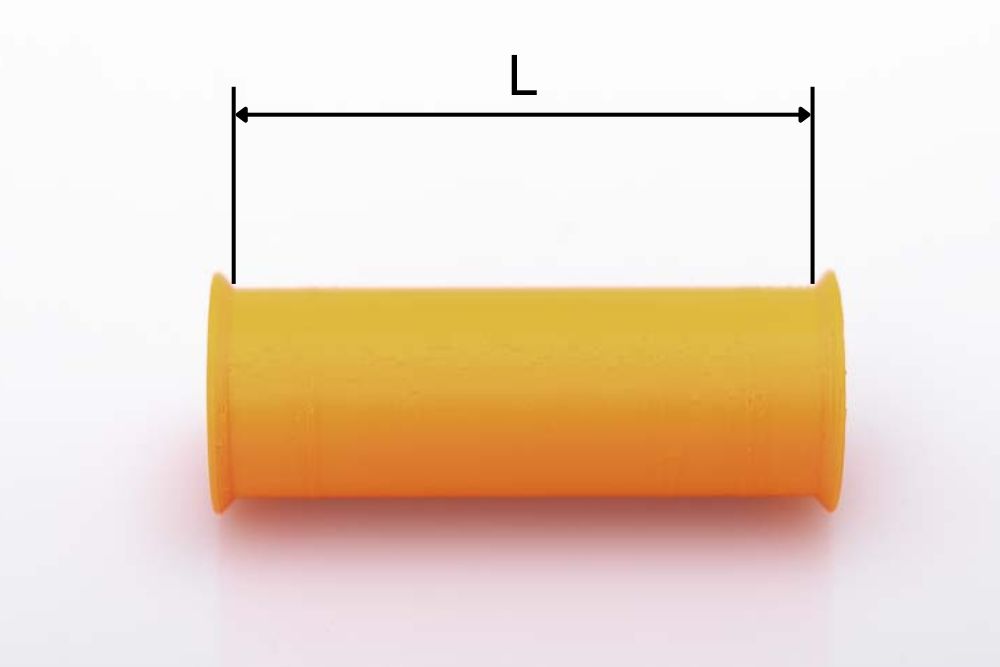
The width of the template refers to the width of the running surface L without brims on the side. See dimensions in photo.
The choice of running tread L depends on the airtight box used or the maximum possible width of the threaded rod. What is important here is the maximum width of the filament spools that will be stored later and of course the number of spools N.
Of course, pulleys of different widths can also be combined to accommodate more spools in one box.

The required rod length is determined according to the formula:
Rod length = 2 * (24+1) + (N-1) * 7 + N * L
The 24 mm results from twice the thickness of the M8 nut (6.5 mm) and the 11 mm wide web of the 3D printed rod mount. The 1 mm is taken into account as additional clearance so that the pulleys are not clamped in later and can rotate easily.
These instructions use an Iris 50L airtight box, which could hold rods up to 485 mm. For example, 5 pcs 80 mm wide pulleys can be used next to each other. If you enter the data N = 5 and L = 80 mm into the formula, a total length of 478 mm is calculated.
In these instructions, the threaded rod is therefore cut into 2 pieces, each 478 mm.
Required 3D printed parts

- 2 pcs 006100_Rod_Mount
Layer height 0.2 mm and 20% infill (rectangular)
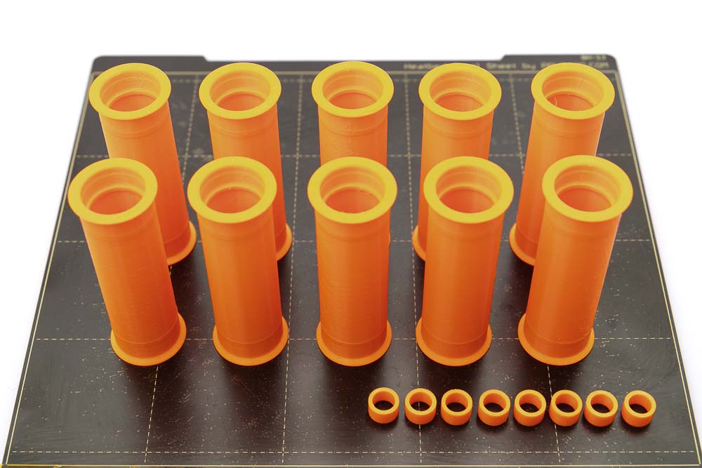
- 10 pcs 006220_Pulley_Wide_L80_F##
- 8 pcs 006300_Spacer
Layer height 0.2 mm and 20% infill (rectangular)
The wide pulley is a PrintFit System part:
The standard 3D print template of the wide pulley is F+0. If the ball bearing cannot be pressed into this version, then print version F+1, whose recess is 0.1 mm larger. If the ball bearing is too loose in the standard version, then print version F-1, which has a smaller hole for the ball bearing.
It’s best to first print just one pulley and press in a ball bearing as a test. If this works without any problems then the remaining parts can be printed.
To press the ball bearings into the pulleys, use the tools provided in the 3D print files. This makes it much easier to press in the bearings and to press them out again if necessary.
Optional for easier installation of the ball bearings in the wide pulleys.
- 1 pc 000400_Tool_Bearing_Press_In
- 1 pc 000600_Tool_Bearing_Press_Counter
Layer height 0.2 mm and 100% infill (rectangular)
Pressing the ball bearings into the wide pulleys
Prepare the wide pulley, two 608 ball bearings and the bearing press-in 3D printed tool.
Put a 608 ball bearing on one side of the wide pulley.
Place the press-in tool and press it firmly with the heel of your hand. Press until the ball bearing is completely pressed against the stop in the wide pulley.
If the ball bearing has been pressed in correctly, it will sit parallel to the pulley and approximately 2.5 mm deep in the pulley.
The ball bearings must sit securely and firmly, as well as parallel and not tilted in the pulleys! Important so that the filament spools do not block later!
Now prepare all remaining pulleys according to the same scheme.
If something goes wrong when pressing in the bearing, or if it needs to be removed from the pulleys, it is best to use a threaded rod and the Bearing_Press_Counter tool. How this works is explained in the chapter Pressing a 608 ball bearing out of a wide pulley in the appendix.
Assembling the filament storage with wide pulleys
Insert one of the M8 threaded rods, shortened to 478 mm, into one of the rod mounts and secure it with two M8 nuts on both sides. To do this, simply use two 13 mm open-ended wrenches. Do not overtighten to avoid damaging the 3D printed part.
The next step is to fix the second rod to the second hole. Afterwards it should look like the photo.
Now put on the pulleys and spacers on the long free side of the rod. Do this in sets of pulley – spacer – pulley, and then repeat.
As in this case, thread a total of 5 wide pulleys and 4 spacers between them.
The spacers prevent that later, when two filament spools run close to each other, a stationary spool is driven from a moving one, or a stationary spool is blocking a moving one.
Check that all adjacent pulleys are separated by a spacer and that the pulleys are not hitting anywhere else.
Repeat on the second threaded rod.
Once all the wide pulleys have been mounted, the end on the second side is prepared. In addition to the second rod mount, you also need four M8 nuts.
Two nuts, one per threaded rod, are now screwed on. It is important that the pulleys are not clamped together, but that they still have a clearance of 1 to 2 mm.
Do not tension the pulleys with the nuts! If the ball bearings are clamped with the nuts, they no longer rotate as easily and the unwinding of the filament spools becomes more difficult or even get blocked.
Thread the rod mount onto the two threaded rods.
Secure the rod mount with two M8 nuts. As before: do not tighten too much so that the 3D printed mount is not damaged.
After attaching the rod mount, check whether the pulleys still have a slight axial clearance (1 to 2 mm) along the rods and can rotate freely. If they are clamped together with the nuts, the rotation of the pulleys will be disabled.
The fully assembled wide pulley version of the filament spool storage.
Congratulations, the filament spool storage is ready. Time for a beer!
Step 2: Mount the filament outlets into the airtight box
The following shows how to build a filament dry box with 6 feedthroughs. Of course, depending on the size of the airtight box or the number of spools to store, fewer or more feedthroughs can be installed.
Required purchased parts

- 1 pc airtight box (shown here is the Iris 50L box used)
Of course, other air-tight boxes can also be used, as already mentioned, please check the dimensions first and adjust the length of the threaded rod and the number of pulleys.
I have 4 of the linked boxes (Iris 50L) in operation and I am very satisfied, they are super air-tight and offer enough space for up to 6 filament spools.
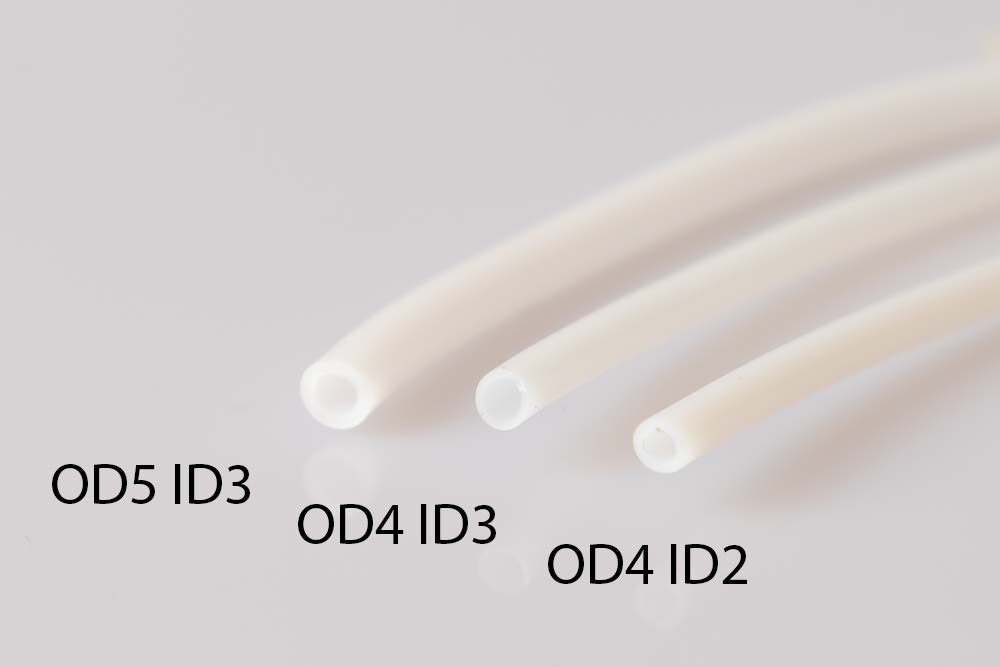
- PTFE tube OD4 ID3
Alternatively, a PTFE tube with an outer diameter of 4 mm (OD4) and an inner diameter of 2 mm (ID2) or an OD5 ID3 tube can also be used.
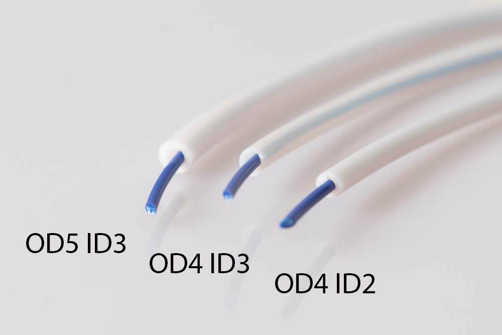
This picture shows the three possible PTFE tube variants with an 1.75 mm filament. It fits well with the ID2, and of course at ID3 there is more space and therefore less friction. This is an advantage if you want to build variant B with long filament guides.
If you build your filament box for 2.85 mm filament you have to choose a PTFE tube with an inner diameter of 3 mm (ID3).
Required 3D printed parts
For variant A – Simple plug
- 6 pcs 006900_Plug_Variant_A_OD4_F##
Layer height 0.2 mm and 100% infill (rectangular)
If an OD5 PTFE tube is used, then print the STL file 007000_Plug_Variant_A_OD5_F##.
The plug variant A is a PrintFit System part:
The standard 3D print template of the plug is the F+1. If the PTFE tube cannot be inserted into this version, then print version F+2, whose conical hole for the PTFE tube is 0.1 mm larger. If the PTFE tube in the standard version is too loose, then print version F+0, which has a smaller bore diameter.
For variant B – Plug is fixed at the filament box
- 6 pcs 007100_Plug_Variant_B_OD4_F##
Layer height 0.2 mm and 100% infill (rectangular)
If an OD5 PTFE tube is used then print the STL file 007200_Plug_Variant_B_OD5_F##.
The plug variant B is a PrintFit System part:
The standard 3D print model of the plug for variant B is the F+2. If the PTFE tube cannot be inserted into this version, then print version F+3, whose conical hole for the PTFE tube is 0.1 mm larger. If the PTFE tube in the standard version is too loose, then print version F+1, which has a smaller bore diameter.
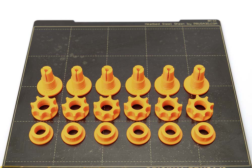
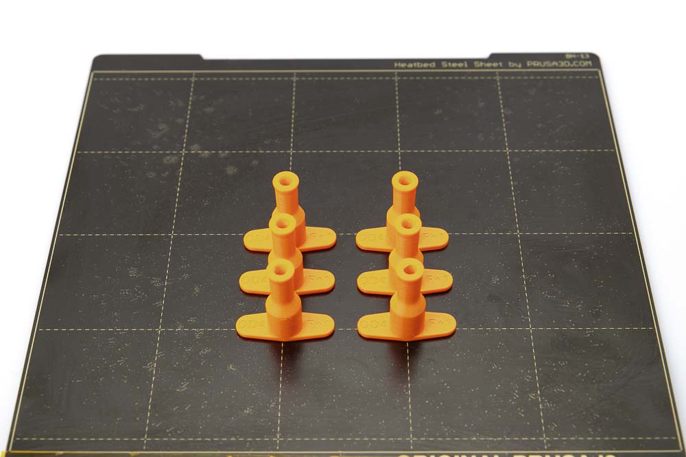
- 6 pcs 006500_Filament_Outlet_OD4_F##
- 6 pcs 006700_Nut_T##
- 6 pcs 006800_Clamping_Ring_W##
Layer height 0.2 mm and 100% infill (rectangular)
If an OD5 PTFE tube is used, then use the 006600_Filament_Outlet_OD5_F## STL file.
It is essential to print these parts (Filament_Outlets) with 100% infill and a mechanically resilient material (PETG, ABS, ASA, etc.). Tests of an external tester have shown that components printed with PLA can break when they are clamped or after a while after assembly.
As a test, pull filament (1.75 mm or 2.85 mm, depending on the design of your box) through the borehole of the printed Filament_Outlets and check for clogging and ease of movement. If necessary, remove print residues or burrs, correct or drill out until all parts for the selected filament diameter run smoothly.
Test printing and assembly of the filament outlet
These 3D printing parts are PrintFit System parts, which means there are STL files in slightly different sizes so that they work even with 3D printers that are not optimally calibrated and with purchased parts that were not manufactured precisely.
It is best to first print just one piece of the standard templates: Filament_Outlet_F+1, Nut_T+5 and Clamping_Ring_W+0 and test the assembly with a short piece of PTFE tubing.
The filament outlet is a PrintFit System part:
The standard 3D print file for implementation is F+1. If the PTFE tube cannot be inserted into this version, then print version F+2, whose hole for the PTFE tube is 0.1 mm larger. If the PTFE tube in the standard version is too loose, then print the F+0 version, which has a smaller bore diameter.
The nut is a PrintFit System part:
The standard 3D printing model of the nut is the T+5. If it is difficult or impossible to screw onto the filament outlet, then print the next larger version T+6, which creates a larger thread gap. If the standard version of the nut is too loose on the outlet then print version T+4, which results in a smaller thread gap.
The clamping ring is a PrintFit System part:
The standard 3D printing template of the clamping ring is W+0. As a test, it is best to print one out and test it with a filament outlet and a piece of PTFE tubing as shown below.
First, a PTFE tube is inserted into the filament outlet and pushed into it until it stops. This should not be too easy or too difficult, otherwise just print a outlet with a narrower or wider hole.
Then push on the clamping ring until it clicks into place and cannot be pressed any further. The cone on the ring presses the toothed clamps inwards onto the PTFE tube, and thereby fixing it.
Depending on the 3D printer setup and manufacturing deviations, it may be that the clamping ring is not flush with the end of the filament outlet. A little deviation (up to 2 mm) is not a problem, but if it is larger, it is advisable to print a clamping ring with other dimensions (e.g.: W+1 or W-1).
If the clamping ring cannot be pushed on as far as the end of the filament outlet, then print the next larger clamping ring W+1. The inner cone has a larger diameter and can be pushed further onto the outlet.
If the clamping ring only engages too far to the printed thread, the 3D printer appears to have printed it too large. Then simply print out the next smaller W-1 clamping ring and repeat the test.
Drill the holes in the air-tight box
The following drilling patterns only apply to the Iris 50L airtight box; for other plastic boxes please measure the appropriate distances yourself. The drilling patterns for Ikea Samla boxes are shown in the quick instructions: Build Ikea Samla Filament Box

For the version with 6 filament outlets, mark the drilling pattern shown on the box using a marker pen. To do this, mark 6 holes in the middle at a horizontal distance of 75 mm and 45 mm above the floor. The bores must have a diameter of 16 mm so that the filament outlets fit cleanly and seal well.
To make life a little easier, Flo created a drilling template to mark the correct distances, here to download on thingiverse.

If, as with the wide pulley version of the box, only 5 holes are required, then drill the holes at a distance of 87 mm in the middle of the airtight box.
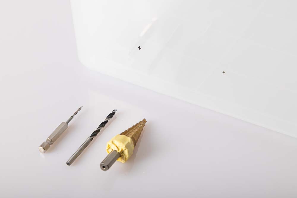
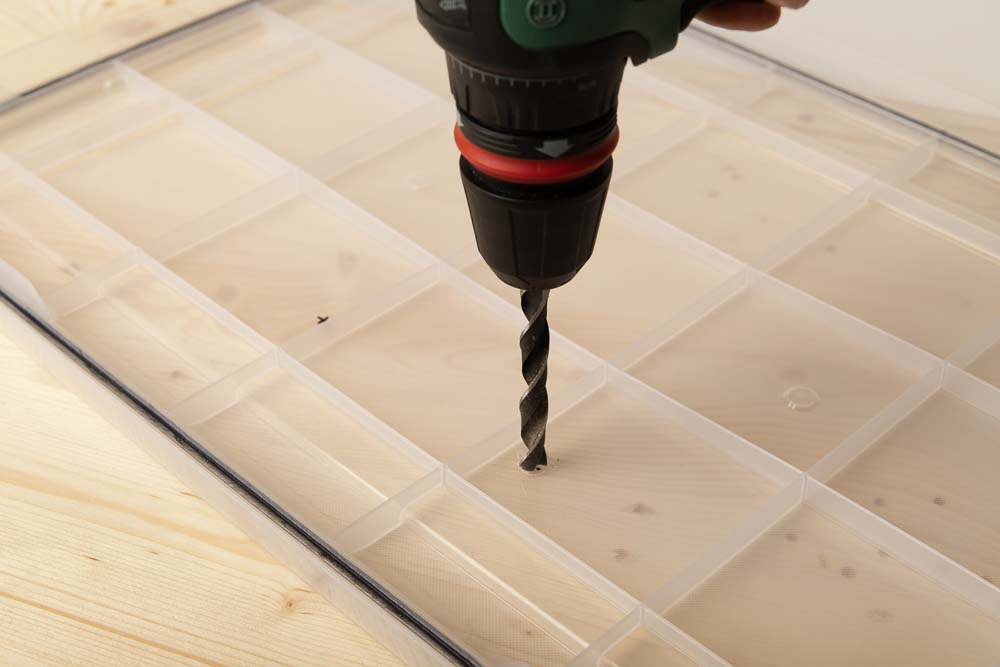
Prepare the cordless screwdriver, 2 mm and 4 mm wood drill bits and the step drill.
On the step drill, all steps larger than 16 mm can be taped off as a precaution – so nothing goes wrong when opening the holes.
Sharp wood drill bits are very suitable for the plastic of the box, it is important to exert only little pressure on the box – too much pressure could break it, so it’s best to pre-drill with the small 2 mm drill and then prepare the hole for the step drill with the 4 mm drill. Use a slow drill speed at step drill and slowly widen the hole.
Wear protective goggles to protect against chips.
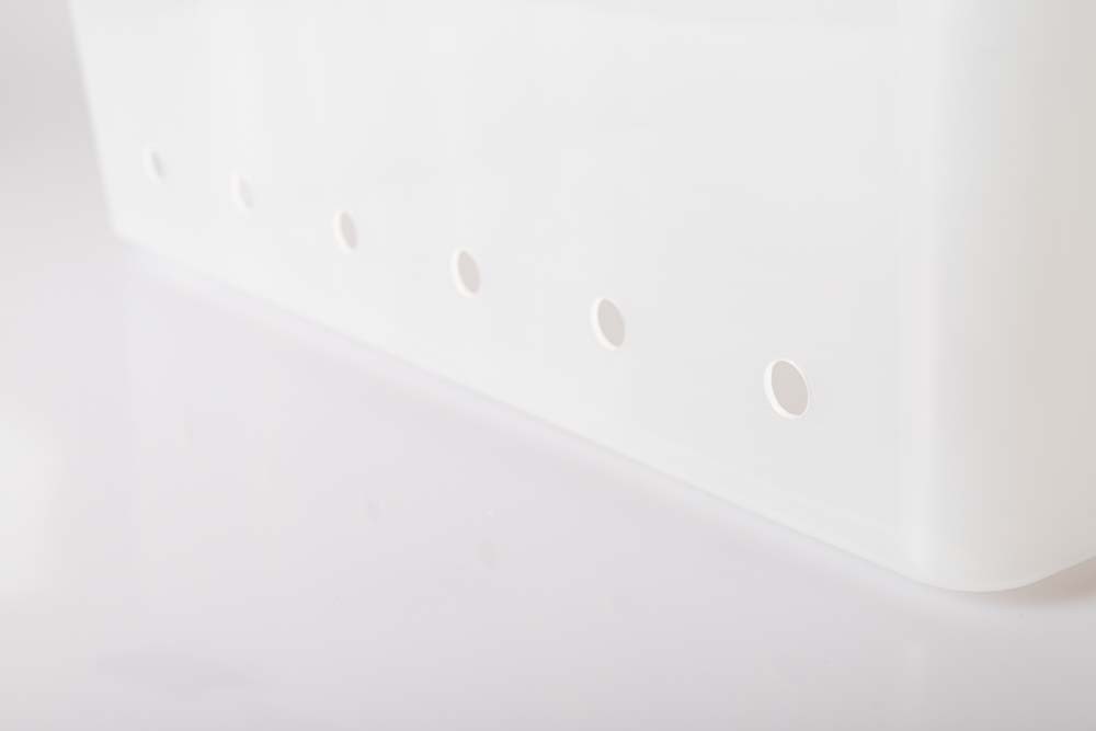
This is what the box should look like with the 16 mm holes.
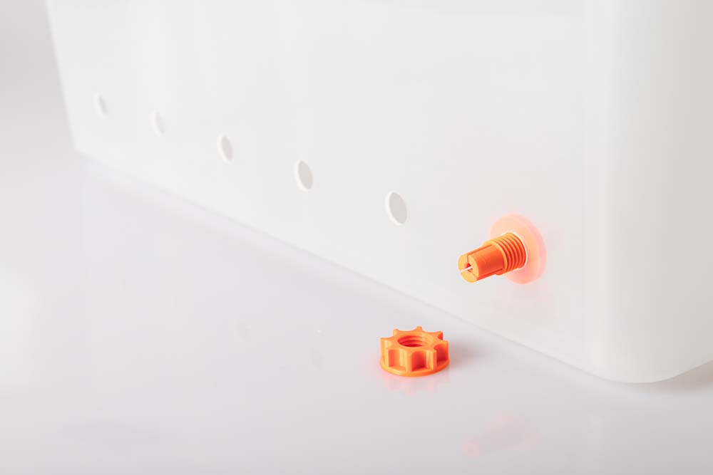
Insert the selected filament outlet from the inside through the hole and screw it with the 3D printed nut from the outside.
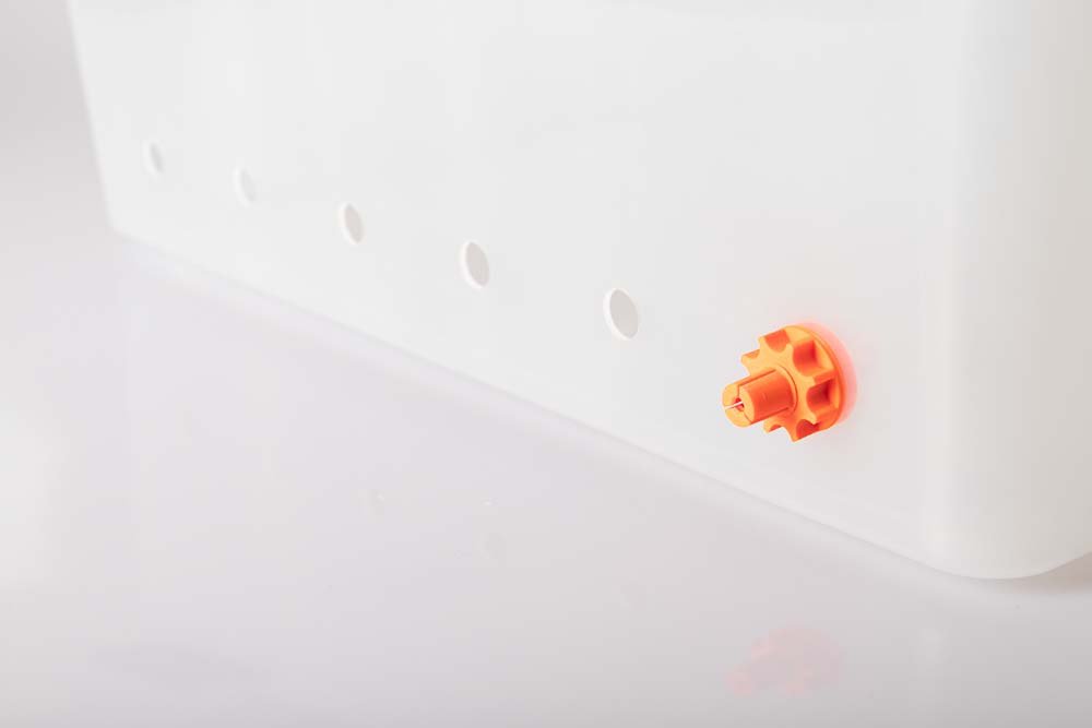
Tighten the nut only by hand – hold the inside against it – check if the filament outlet is pulled completely into the hole.
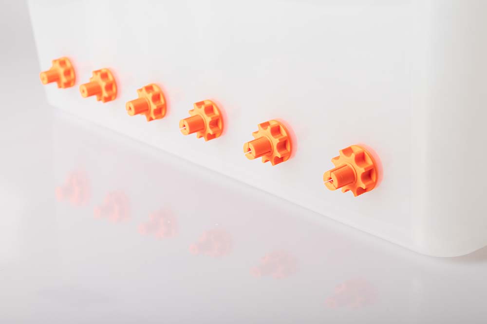
Repeat this for the other 5 filament outlets.
Now it’s time to attach the PTFE tubes, here you can choose between two variants. Regardless whether variant, A or B it’s still very easy to switch between the two variants later, you are able to print the required components with only a few grams of filament.
Variant A – Simple plug
First, variant A with the short tubes are shown, variant B will be discussed immediately afterwards.
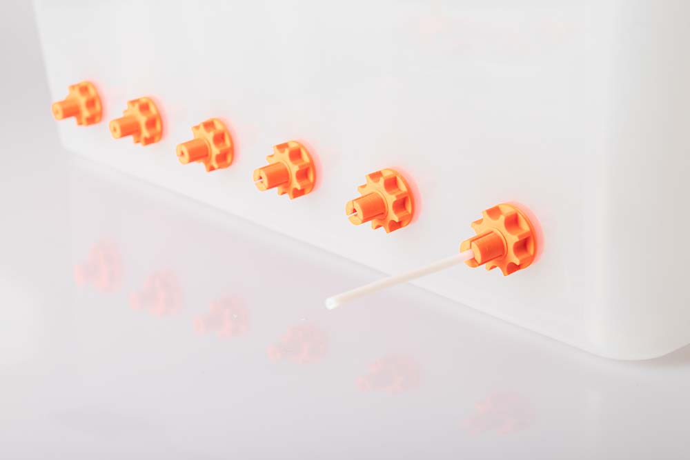
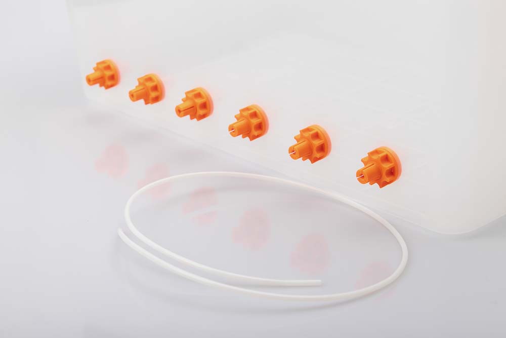
Cut the selected PTFE tubes into short pieces of 10 to 20 cm using a box cutter. Make the cut neatly straight. Push the pieces of tubing into the filament outlets until they are stopped on the inside edge, some force is required.
Use cut-resistant underlay, wear work gloves.
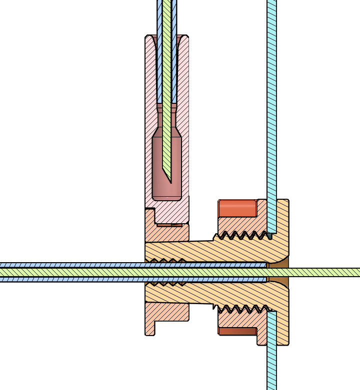
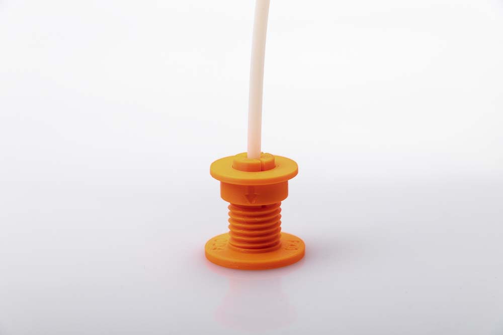
If the tube is fully inserted in the outlet, it is fixed with a clamping ring. The cone of the clamping ring is pushed over the cone of the toothed gripper of the outlet and thus clamps the tube. When pressing on, always hold the outlet on the inside of the box against the pressure. The embossed arrow on the clamping ring must point towards the filament box.
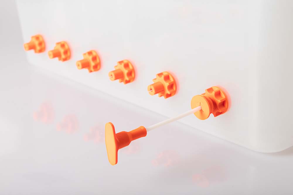
The PTFE tube is sealed by the 3D printed plug, due to a cone on the inside which also clamps the plug on the tube.

Repeat for the remaining filament outlets.
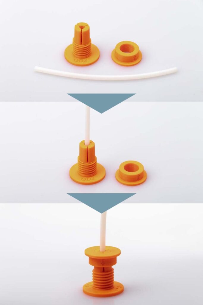
Variant B: Plug is fixed at the filament box
Use a box cutter to cut the selected PTFE tubes into long pieces, depending on needed length to the printer, in this example it’s 90 cm. Make the cut neatly straight.
Make the cut clean and straight.
Use cut-resistant underlay, wear work gloves.
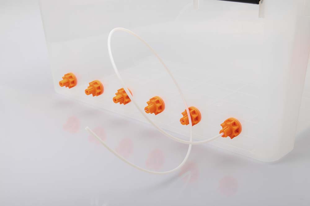
Push the tubes into the filament outlets until they line up on the inside of the outlet.
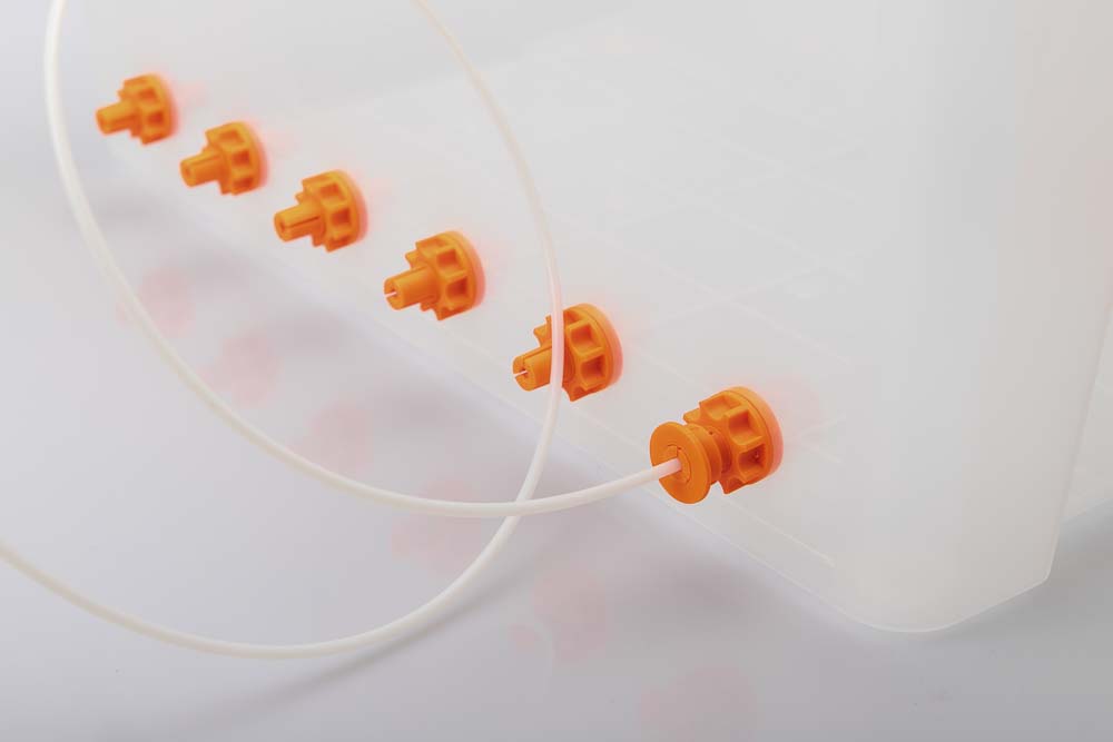
If the tube is fully inserted in the filament outlet, it is fixed with the clamping ring. The cone of the clamping ring is pushed over the cone of the toothed gripper of the outlet and thus clamps the tube. When pressing on, always fix the filament outlet on the inside and hold against it. The embossed arrow on the Clamping_Ring must point in the direction of the box.
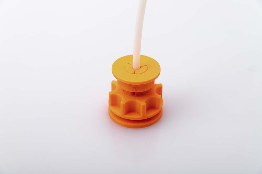
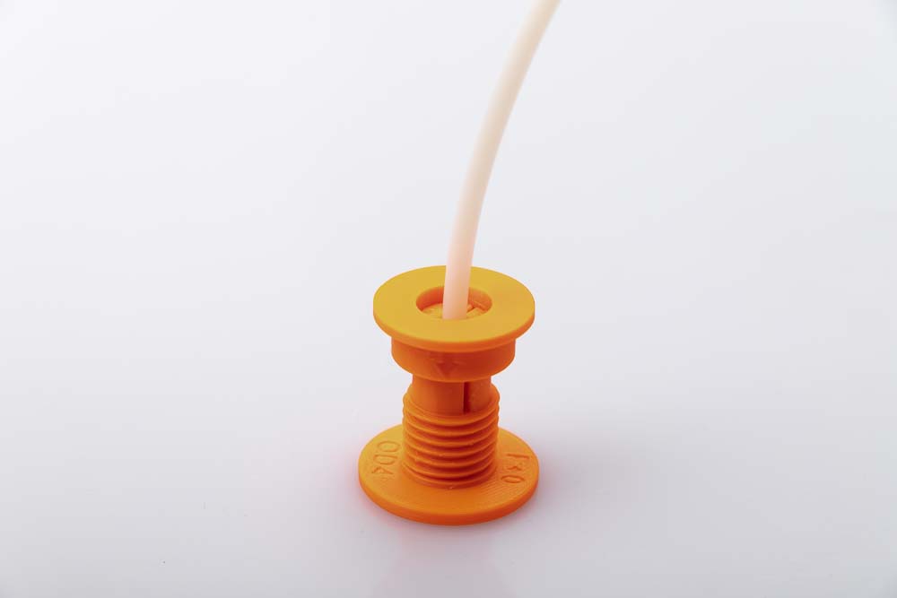
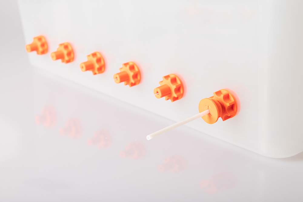
The long PTFE tube is then sealed by simply pressing it from above into the 3D printed plug, sealing it with a cone on the inside and at the same time fixing it.
Now repeat the procedure for all remaining filament outlets.
The clipped-on plugs of variant B can also be fixed with super glue for a better hold. To do this, simply coat the clamping ring with a little super glue and clip on the plug.
With this variant, always make sure before printing that the PTFE tube cannot be pulled or squeezed into the extruder or the mechanics on the 3D printer.
Filament signs for labeling the loaded material on the box
Once you operate more filament boxes, it is easy to lose track of the stored filaments. Above all, which type of filament (ABS, PETG, PLA, etc.) is loaded in which dry box is important for the print job. For this reason, optional filament labels can be printed out and attached to the filament outlets.
There are 21 different material type labels available! If a certain material is still missing, please just write me at support@3d-druck-vorlagen.de
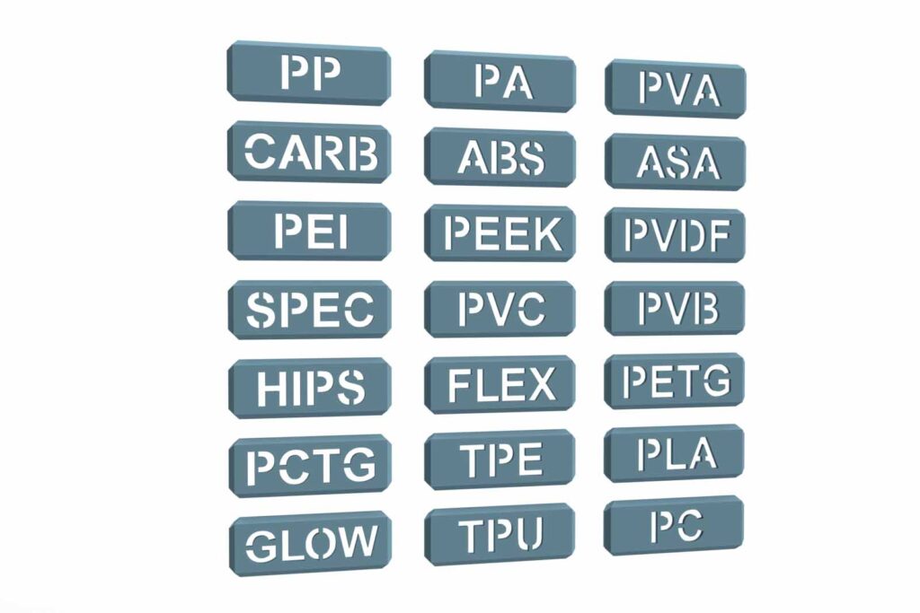
Included are signs for:
- ABS
- ASA
- CARB – for carbon fiber reinforced filaments
- FLEX – for flexible filaments
- GLOW – for fluorescent filaments
- HIPS
- PA
- PC
- PCTG
- PEEK
- PEI
- PETG
- PLA
- PP
- PVA
- PVB
- PVC
- PVDF
- SPEC – for special filaments
- TPE
- TPU
Required 3D printed parts
It’s best to print the signs straight away with the filament that is also stored in the box. The respective spool is then marked with an illustrative part, where the quality and color of the stored filament can be clearly seen.
3D print the material labels
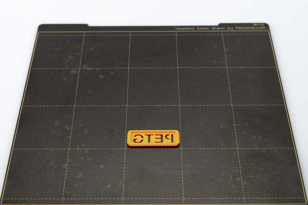
- 1 pc 009600_PETG_Sign
Depending on which material is to be stored later, select the appropriate sign, for example PLA, PC, ABS, TPE, etc.
Layer height 0.2 mm and 100% infill (rectangular)
Contrast plate
The contrast plate is clamped behind the sign and thus determines the font color of the material labels. It is also the connection from the sign to the clip, which in turn is attached to the box.
Choose the color for the contrast plate to match the color of the printed sign. If the filament color of the sign is rather light, it is best to print in black filament. A white contrast plate is recommended if the printed sign has a dark color or is black.
- 6 pcs 008400_Contrast_Plate_F##
Depending on the signs printed in light or dark filament and in the number as required.
Layer height 0.2 mm and 100% infill (rectangular)
The contrast plate is a PrintFit System part:
The standard 3D printing template of the contrast plate is the F+1. If this cannot be clipped into the printed sign, then print version F+2, whose gap to the sign is 0.1 mm larger. If the sign sits too loosely on the contrast plate, then print version F+0, which has a smaller gap to the material sign part.
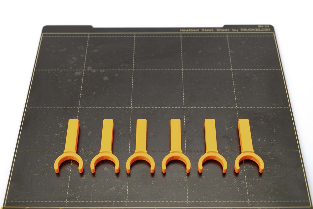
Fastening clip
Depending on the variant built, there are different clips for attaching the signs to the filament outlets. For variant A with a short PTFE tube, print out the clips variant A. For variant B, print out the clips variant B.
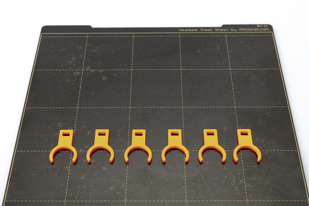
- 6 pcs 008200_Clip_Variant_A
Layer height 0.2 mm and 100% infill (rectangular)
- 6 pcs 008300_Clip_Variant_B
Layer height 0.2 mm and 100% infill (rectangular)
Assembling the material sign and contrast plate
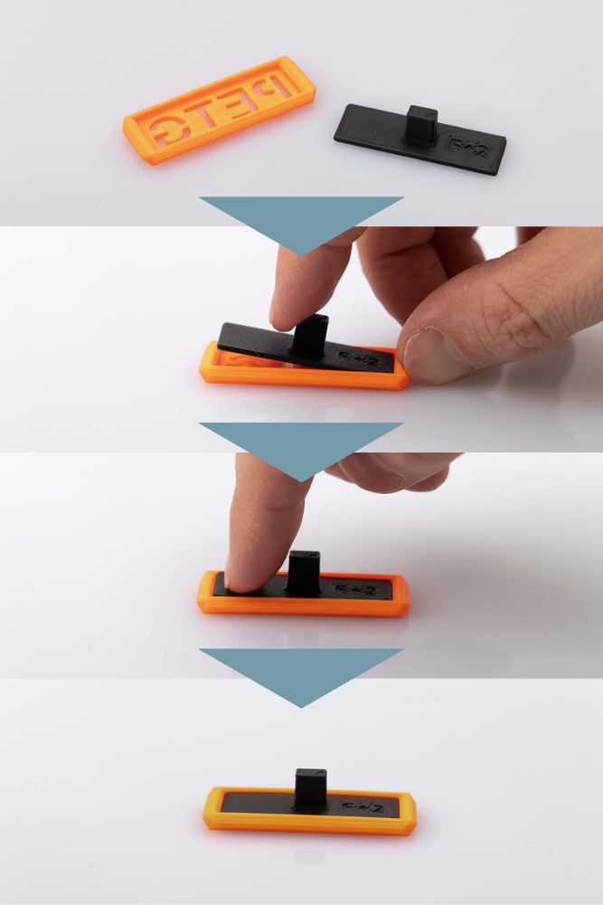
Assembly is very easy, place the material plate upside down on the table and clip the contrast plate in from behind as shown. If it is too loose or does not fit into the sign, simply print the next smaller or larger STL file of the contrast plate.
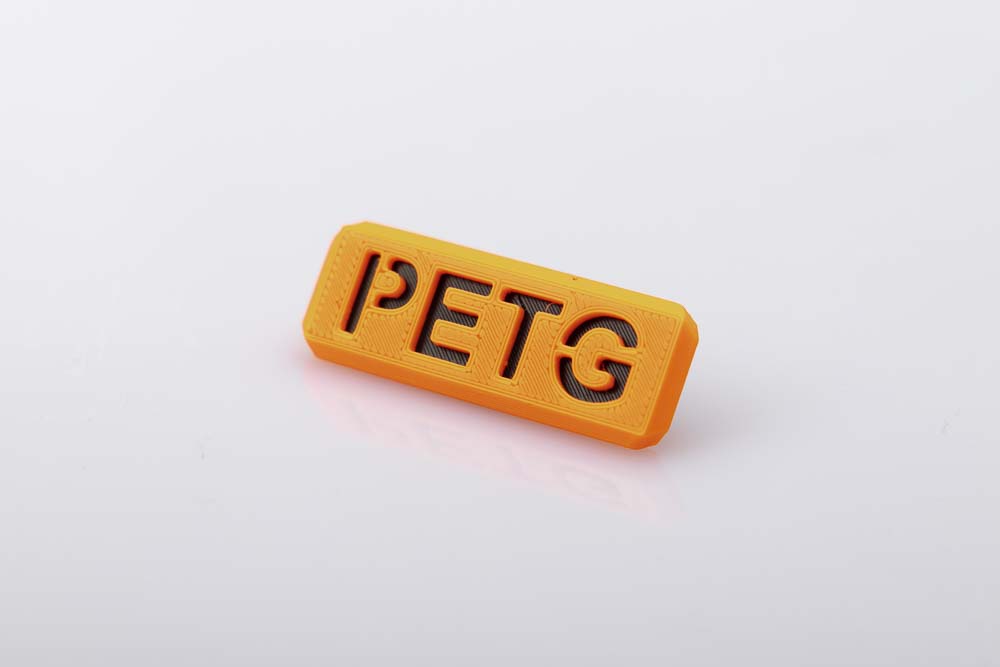
Orange PETG filament sign with black contrast plate.
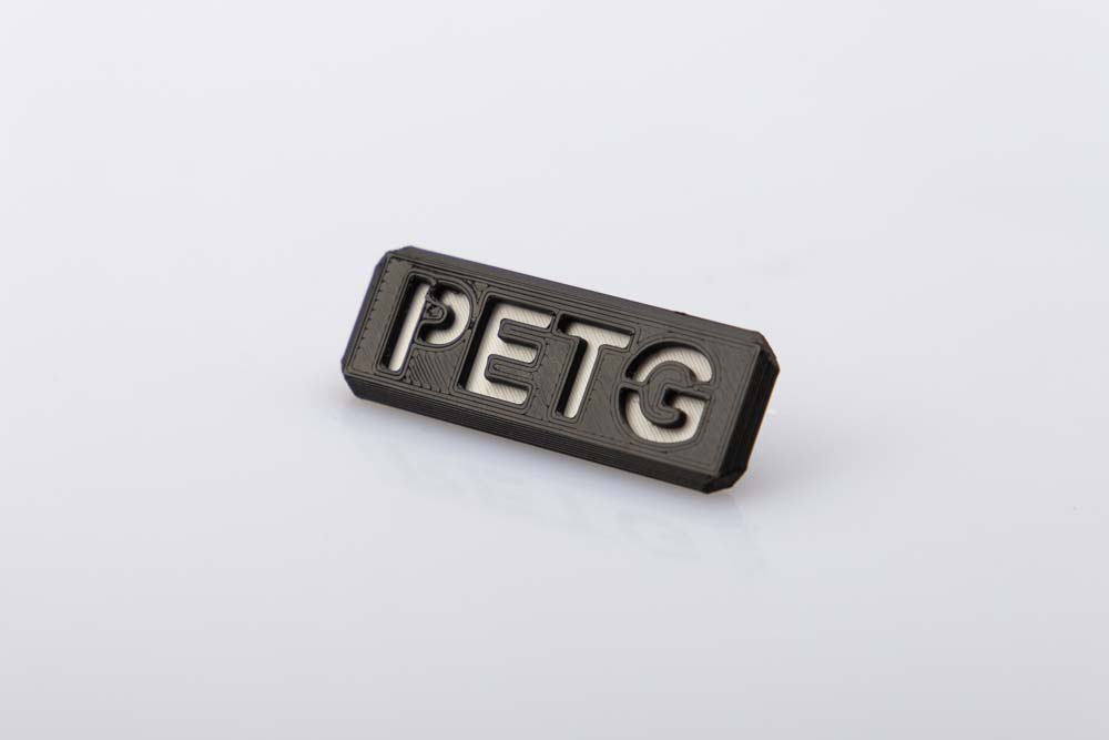
Black PETG filament sign with white contrast plate.
Attaching the material labels to the filament box
As described, depending on the version built, the suitable clip is required for variant A or variant B.
Assembly material label with clip on variant A
To attach the material labels, attach the clip variant A to the clamping ring of the filament outlet. Then insert the material label including the contrast plate into the opening provided on the clip. The sign is fixed to the clip by the slight cone on the contrast plate.
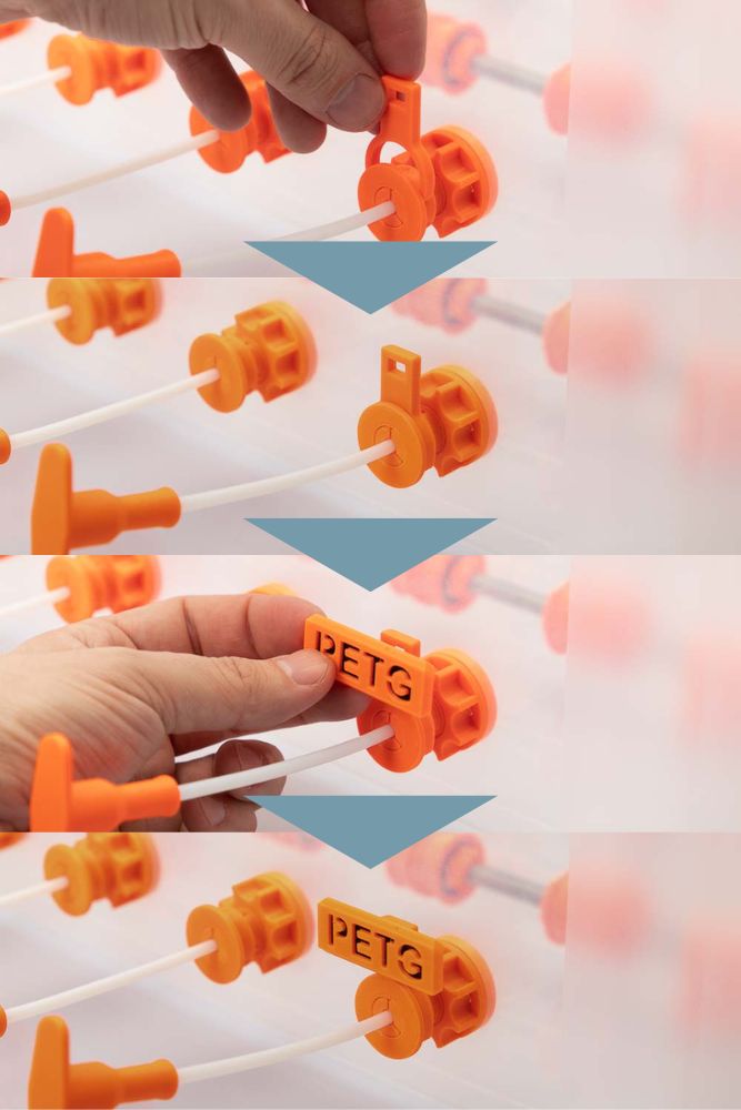
Assembly material label with clip on variant B
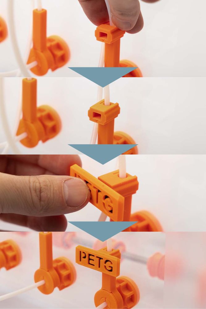
To attach the material labels, attach the clip variant B to the tube plug. A small triangle on the front of the clip shows the direction of attachment. Then insert the material label including the contrast plate into the opening provided on the clip. The sign is fixed to the clip by the cone on the tenon of the contrast plate.
Very good, the most difficult part is done and the filament box is almost ready!
Step 3: Tape the filament spool storage into the filamet box
In order to prevent the filament spool storage from slipping in the filament box, it is recommended to fix the two rod mounts in the box with double-sided adhesive tape.
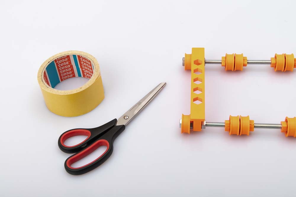
All you need is scissors and double-sided tape.
Cut the tape so that it fit under the filament spool storage. Remove the protective film and stick the filament holder in the rear half of the filament dry box.
When positioning, it is best to insert the largest spool of filament to be stored and to check if it hits the back wall of the airtight box.
Leave enough distance to the walls of the box and after gluing in, test whether the largest spool of filament to be stored can rotate freely. Otherwise change position and test again.
Done, now all that’s missing is the filament box lid with the integrated silica gel holder to finish your dry filament storage box.
Step 4: Attach silica gel bag holder to the lid
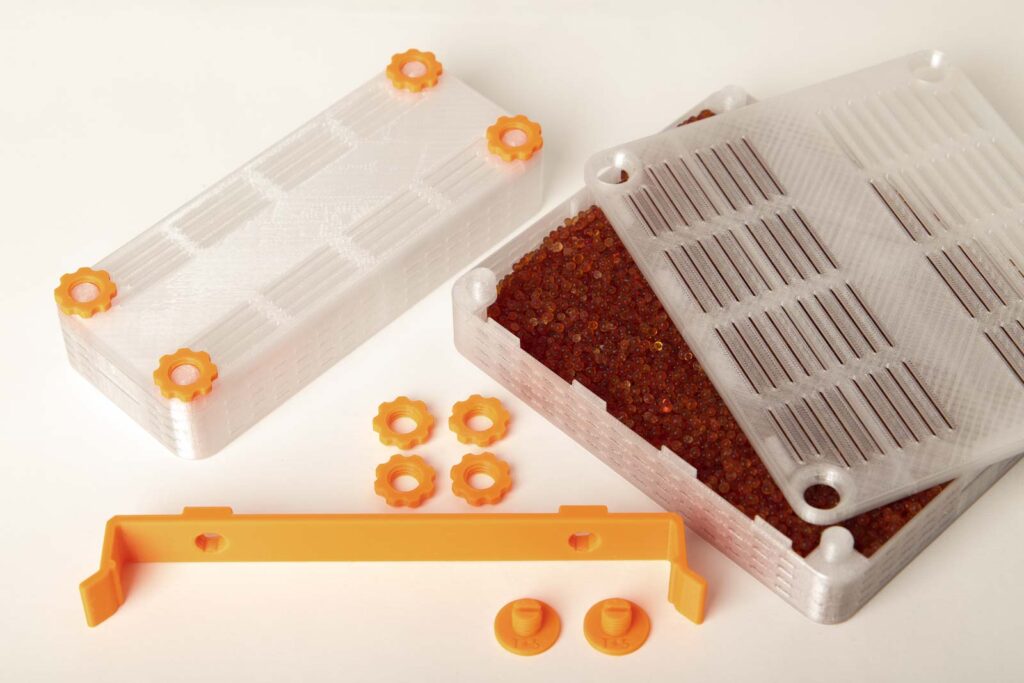
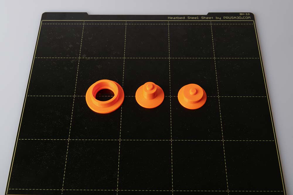
The last thing to prepare is the lid. A bag of silica gel (desiccant) is stored here so that it does not interfere with the filament spools when rotating. There is also the option to use loose desiccant that is housed in a 3D printed box, check the instructions to the DIY silica gel box.
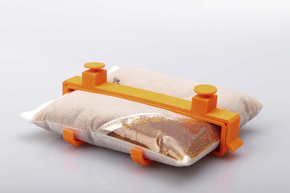
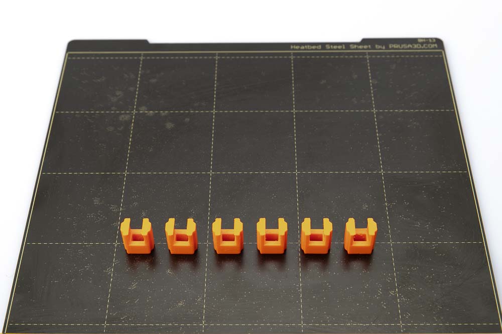
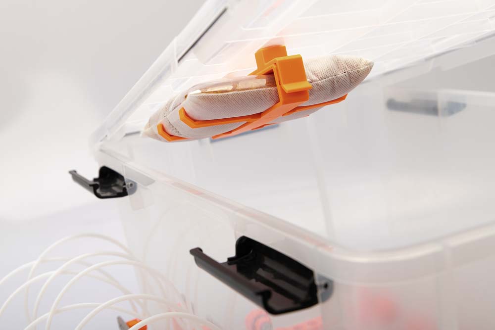
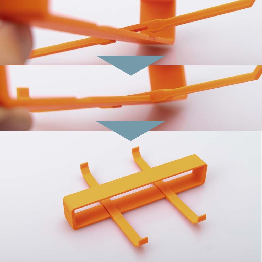
Using a 3D printed retaining clip, the silica gel bag is clipped and held on the lid of the filament dry box. By bending the clip sideways, the bag holder can then easily be removed from the lid. This means that the desiccant can be regenerated and simply reinserted into the clamp later.
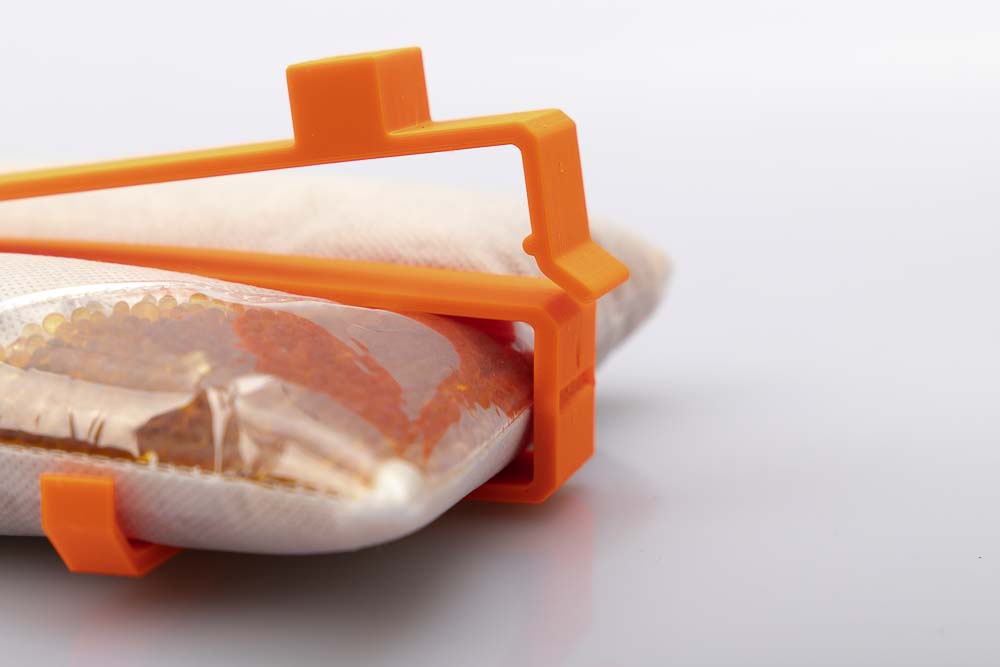
The retaining clip, which is later mounted in the lid, is ready to clip in the silica gel bracket.
Desiccant holder clipped into the retaining clip.
Required purchased parts
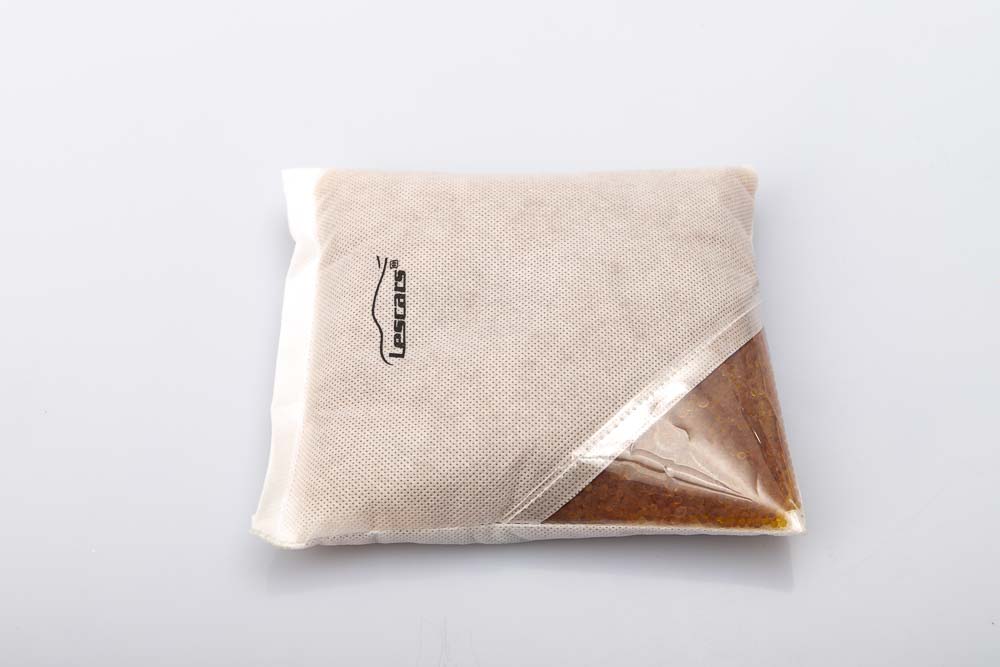
- 1 pc Silica gel bag approx. 15 x 17 x 3 cm
Required 3D printed parts
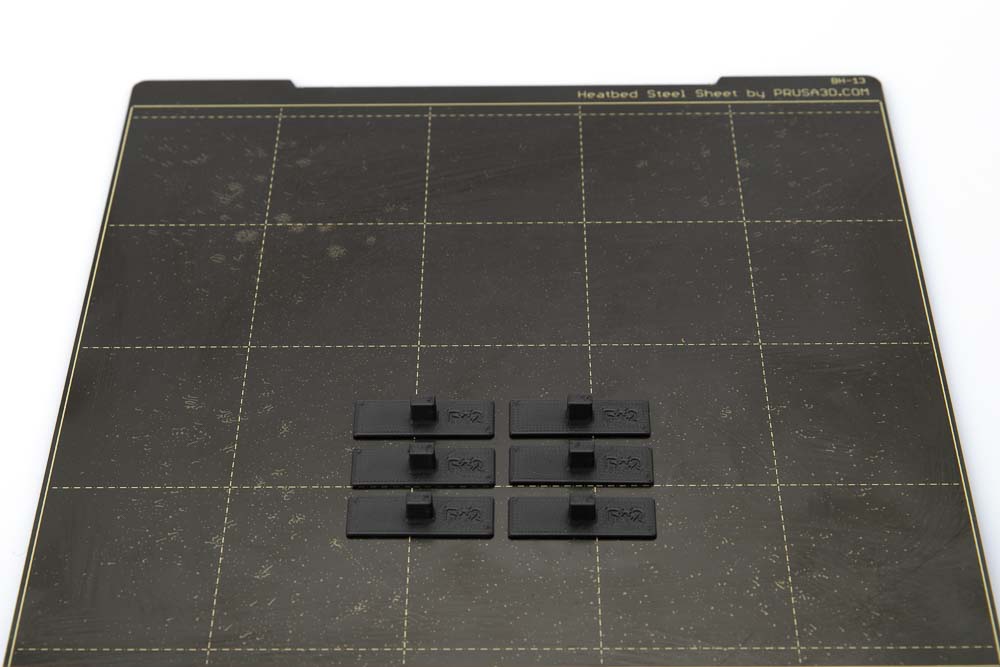
The retaining clip is available in two versions. If the clip is later mounted in the Iris 50L airtight box then print the H12 version as this can be mounted in the ribbed lid. If your filament box does not have a ribbed lid then use version H3.
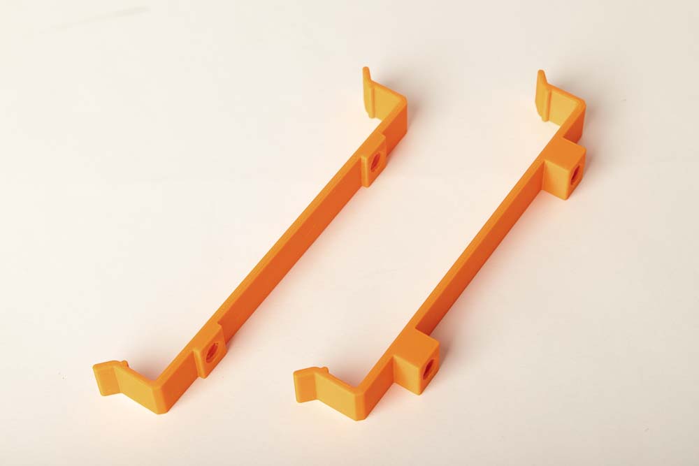
The photo shows the two possible versions of the clip. On the left you can see the Clip_H3, which has 3 mm high bars and can be mounted in covers without ribs. On the right you can see the Clip_H12, which has 12 mm high bars, suitable for lids with ribs.
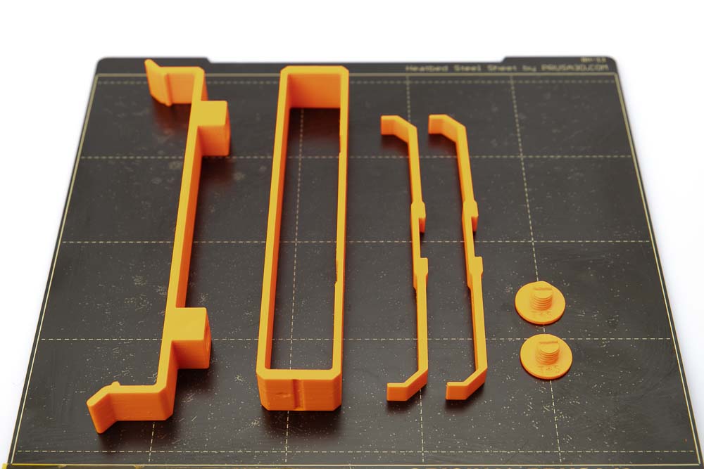
- 1 pc 007300_Silica_Gel_Clip_H12
- 2 pcs 007400_Silica_Gel_Screw_T##
- 1 pc 007500_Silica_Gel_Bag_Bracket
- 2 pcs 007600_Silica_Gel_Bag_Side_Support_F##
Layer height 0.2 mm and 100% infill (rectangular)
The screw is a PrintFit System part:
The standard 3D printing template of the screw is the T+5. If it is difficult or impossible to screw into the clip, then print the next larger version T+6, which creates a larger thread gap. If the standard version of the screw is too loose then print version T+4, which results in a smaller thread gap in combination with the clamp.
The side support is a PrintFit System part:
The standard 3D print model for the side support is F+0. This part will later be clipped into the bracket. If it is difficult or impossible to clip into the bracket, then print the next larger version F+1. In this 3D printing template, the recess is 0.1 mm wider. If the standard version of the side support does not sit securely in the bracket, then print version F-1, whose recess is 0.1 mm smaller than the width of the bracket.
Assembling the silica gel holder for the filament box
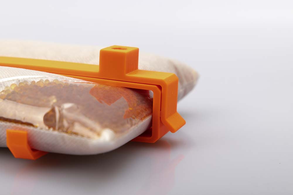
To ensure that the desiccant bag holds well in the lid, the holder is put together first.
Clip the two side supports into the bracket. To do this, insert the side support into the recess provided in the bracket on one side and press it down. Repeat for the second side support.
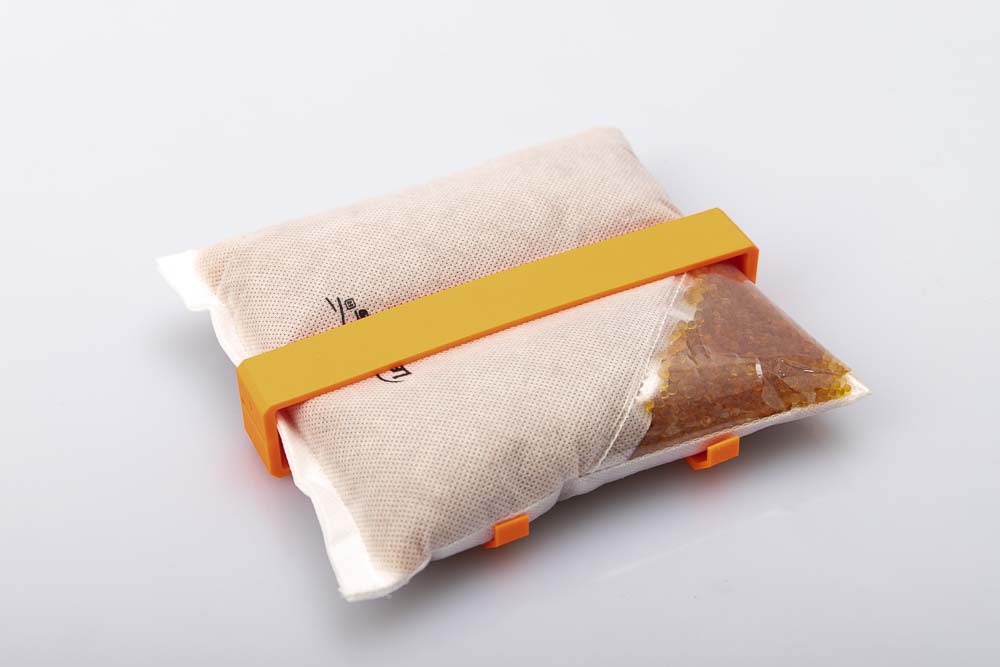
Push the 500 g silica gel bag into the holder until it sits in the middle. Make sure that it is limited by the side supports and sits well.
Mounting the clip in the lid of the filament box
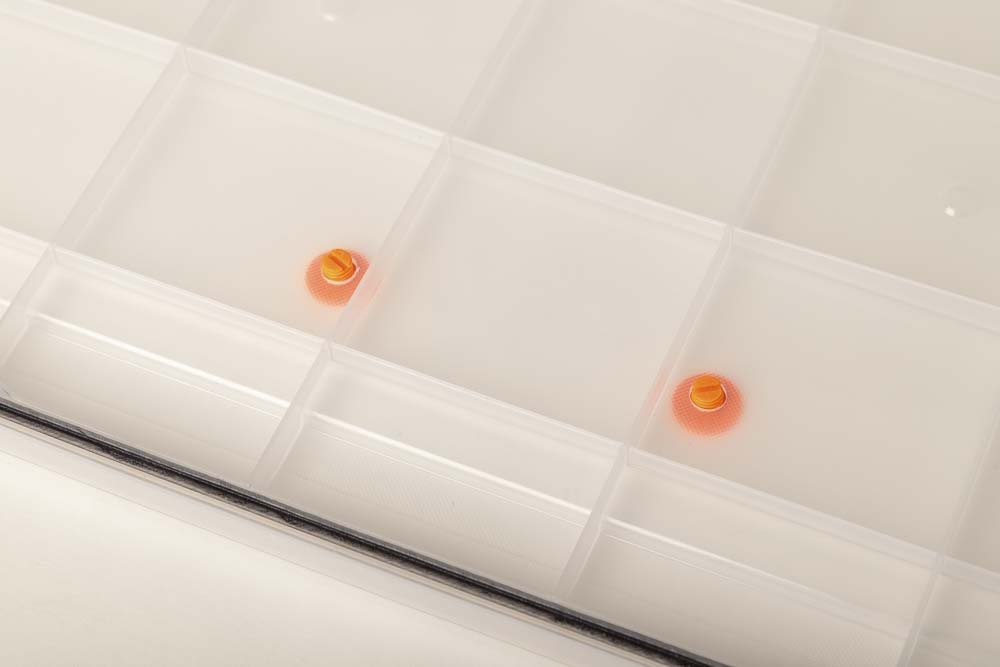
First, two 10 mm diameter holes must be drilled in the lid. The distance between the holes must be 115 mm. The distance from the front edge should be at least 100 mm.
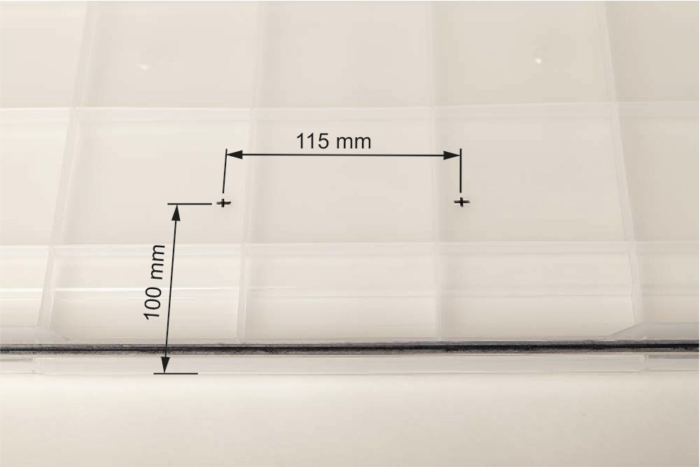
For the Iris 50L airtight box, the holes must be at least 100 mm from the front edge.
Place the markings in the middle of the lid.
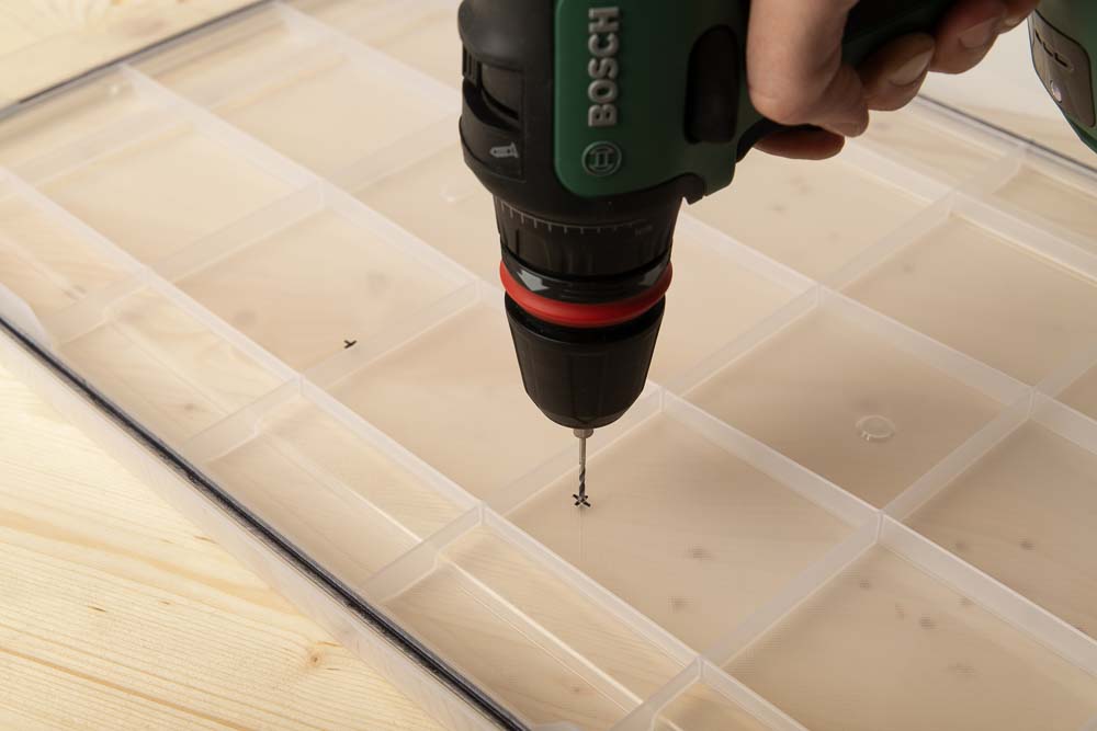
If the holes to be are marked, it is best to place a piece of sacrificial wood underneath and first pre-drill with the 2 mm wood drill.
Then drill the final holes with the 10 mm wood drill.
Again it is best to pre-drill the holes with the 2 mm wood drill bit and then set the final holes with the 10 mm wood drill. Drill slowly so that the cover is not damaged when it is pierced.
Wear safety glasses to protect yourself from chips!
Insert the 3D printed screws through the holes from the outside.
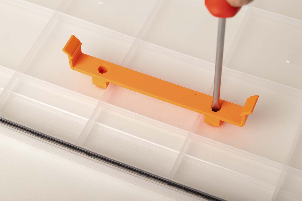
Place the printed clip on the screws and tighten from the outside by hand or from the inside with a flathead screwdriver. Do not overtighten, so that the 3D printed parts are not damaged.
If a screwdriver is used, remember that the screws from the inside should not be tightened “clockwise” but “counterclockwise”.
Check that the clip is screwed tightly and correctly. The clip must not come loose when the filament box is in operation.
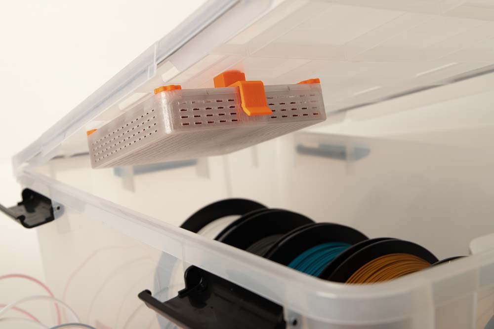
Inserting the silica gel holder in the lid
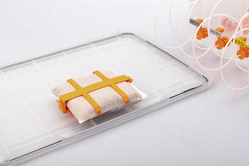
Insert the silica gel holder in the middle of the clip on the lid and let it snap into place.
Put the lid on the box and check whether the holder and the silica gel bag are seated properly.
Check the stability of the screwed clip and the secure fit of the silica gel bag. It must not come loose when operating the filament dry box.
Step 5: Load the finished filament box and test it
Thread the filament of the filament spools to be stored into the filament outlets and adjust the pulleys to the width of the filament spools. Gradually insert all the spools and then close with the lid.
When inserting the filament spools, check that they can rotate freely and that they do not touch the floor or the walls of the storage box – if a spool scrapes or blocks, this one is not suitable for the filament storage box.
If the filament blocks or can only be pushed through the outlet under a lot of pressure, the outlet and the PTFE tube must be checked for blockages or too small bore diameters and cleaned or replaced.
Inserting and threading the filament is described in the Operating manual of the DIY filament box in more detail.
Congratulations! It’s done, your filament dry box is ready for use!
Before operation, it is important that you also read the Operating manual of the DIY filament box and the safety instructions listed there! The silica gel needs to be regenerated approximately every 3 to 6 months. Have fun printing!
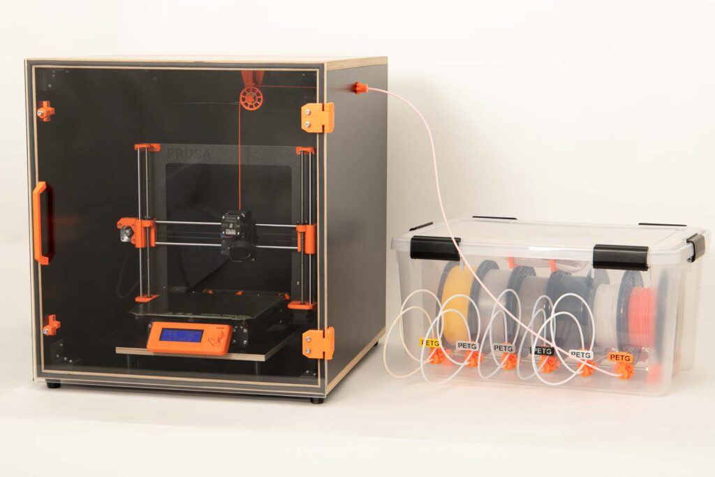
The filament dry box also works perfectly in combination with the DIY 3D printer enclosure, the filament which should be printed can be easily plugged in and out. The 3D print files of the DIY 3D printer enclosure can be found in the web shop.
Disclaimer
The instructions and the associated files are an inspiration of Ingenieurbüro Dr. Janko GmbH to build this project yourself. Since Ingenieurbüro Dr. Janko GmbH has no way of checking and influencing the required quality of the printed components and purchased parts as well as the quality of the assembly and the correct functioning of the project or if any inadmissible changes and modifications to the project has been made, Ingenieurbüro Dr. Janko GmbH accepts no liability for functionality, stability or damage incurred by the project.
Appendix – Additional tipps and tricks
Pressing a 608 ball bearing out of a single pulley
If something went wrong while pressing in or if the ball bearings should find a place in another project, the process of pressing out a bearing is shown here. With the aid of the inculded 3D printed tools it is quite easy.
In order to remove a pressed-in ball bearing from a pulley, the 3D printed parts Tool_Bearing_Press_Out and Tool_Bearing_Press_Counter are required.
Place the pulley on the counter so that the open side faces down towards the desk. This allows pressing out the ball bearing and to fall into the counter part.
Place the press-out tool in the middle of the ball bearing and press firmly,
until the ball bearing is fully pushed out.
The ball bearing is already removed from the pulley and can be removed from the counter part.
Pressing a 608 ball bearing out of a wide pulley
Pressing the ball bearings out of the wide pulleys works a little differently than with the single pulleys. In addition to the 3D printed tool Bearing_Press_Counter, a threaded M8 rod is also required.
In order to remove the ball bearings from the wide pulley, the 3D printed part Tool_Bearing_Press_Counter, a M8 nut, and a threaded M8 rod are required.
Place the wide pulley on the press-out counter so that the two cylinders are concentric. This means that the pressed out ball bearing can then fall into the 3D printed counter.
Pass the threaded rod through the upper ball bearing and guide it slightly at an angle to the lower ball bearing.
Then press lightly, change position a little if necessary and press again. Repeat until the lower ball bearing completely falls out of the pulley.
Once the ball bearing has been pressed out, remove the wide pulley from the counter and remove the ball bearing from it. Check the ball bearing to see whether it was damaged by pressing out.
The second ball bearing can then be pressed out quite easily. To do this, screw the M8 nut onto the threaded rod until a little of the threaded rod protrudes on one side.
Place the wide pulley, which now only has one ball bearing, back onto the press-out counter and insert the threaded rod with nut from above. Then press on the threaded rod until the ball bearing falls into the counter.
Done, now the second ball bearing has been pressed out of the wide pulley.
in the top image of the box there are different fasteners than the ones in the STL, wider ones , can you provide those stls as well ?
Hi Doronazl,
thank you for your comment! The fasteners at the top picture are the ones that already come with the box which is linked in the BOM (purchase parts list). The fasteners in the 3D print files are perfectly tailored for the IKEA Samla boxes (22l and 45l version, which came without fasteners, but therefore are cheaper).
Best regards and happy printing
Marian
Hey. Your project is detailed and amazing.
I have a question. Why you didn’t use a heater to control temperature and humidity ?
Hello Antonio,
thank you very much for your praise and comment! Never thought of that, because I directly store the unpacked filament spools in the air-tight silica gel filled filament boxes – so I never got any problem with wet filament. If some filament gets wet, I think it’s better to dry it in a specialized filament dryer or oven. It would of course be super exciting to do such a project, unfortunately I’m always so short on time 😉
Happy printing and best regards
Marian
I would like to know if you coud create a 65mm wide pulley. 60 was just a bit too narrow and 70 was a bit too wide.
Hi Jonathan!
Thanks for your feedback, I did a quick parameter change in Fusion for the 65 mm wide pulleys. Just sent them to you via email!
Happy Printing and Happy New Year!
Best regards
Marian
Everything is nice and clear. I just started the build this tool and its so easy to undertand the process and build the box. This model can fit any box you can find. Thank you for this awesome work!
Hi Cemal,
thank you very much for your comment! I just checked your website – to everyone: check his awesome 3D printed RC planes on https://craycle.com/!
Happy printing!
Marian
Are the STLs available to purchase in the US yet? I would like to make one of these for my work 3D printer material.
Hi Grace,
yes they are now available worldwide!
Happy printing! Marian
P.s. If you got any questions don’t hesitate to ask me: support@3d-druck-vorlagen.de
Do you recommend adding heat ro help with drying HAS anyone did that.
Hi Kelly,
adding heat to the filament is recommend when it has already soak water from air. If you keep your filament always dry, like in my filament box (airtight and silica gel to secure a super low moisture level) your filament is not going to soak water from the air. So you won’t need to add heat to get rid of the water inside the filament.
If the filament already is wet you going to need heat to get rid of the water inside, like you said. Some use food dehydrators or an oven, there are a lot of instructions for that at youtube etc.
Hope this helped, best regards and happy printing!
Marian
i need a source for the storage tote in the us or anywhere?
Marian,
I built this dry box V2 and wanted to thank you for this fantastic job with 3d design and detailed instructions (including bill of material and recommended tools, I’m not used to such precision level).
I had much fun printing and building it and it works really well.
Now humidity in the box is around 17% and print quality is much better indeed.
Kudos !
Hi Yves,
thank you very much! Yes I try to make it as professional as possible – hope I got soon some time to finish the next projects and upload them. Yeah I love the filament boxes too, got now 4 of them in operation and also got no problems with moisture so far.
Happy printing, best regards!
Marian
Same here. Would love to get access to these, they seem very well made.
I am located in Canada can I purchase these STLs and or make a donation that might get me access. 🙂
Hi Jesse,
thank you for your interest in the Filament Box. It’s a legal thing right now that I only sell in the European Union Countries – but I’m working on expanding this to worldwide. Unfortunately this is going to take some time, but I’m going to set you on a list and inform you if I can open the shop to US.
Till then enjoy printing, best regards Marian