

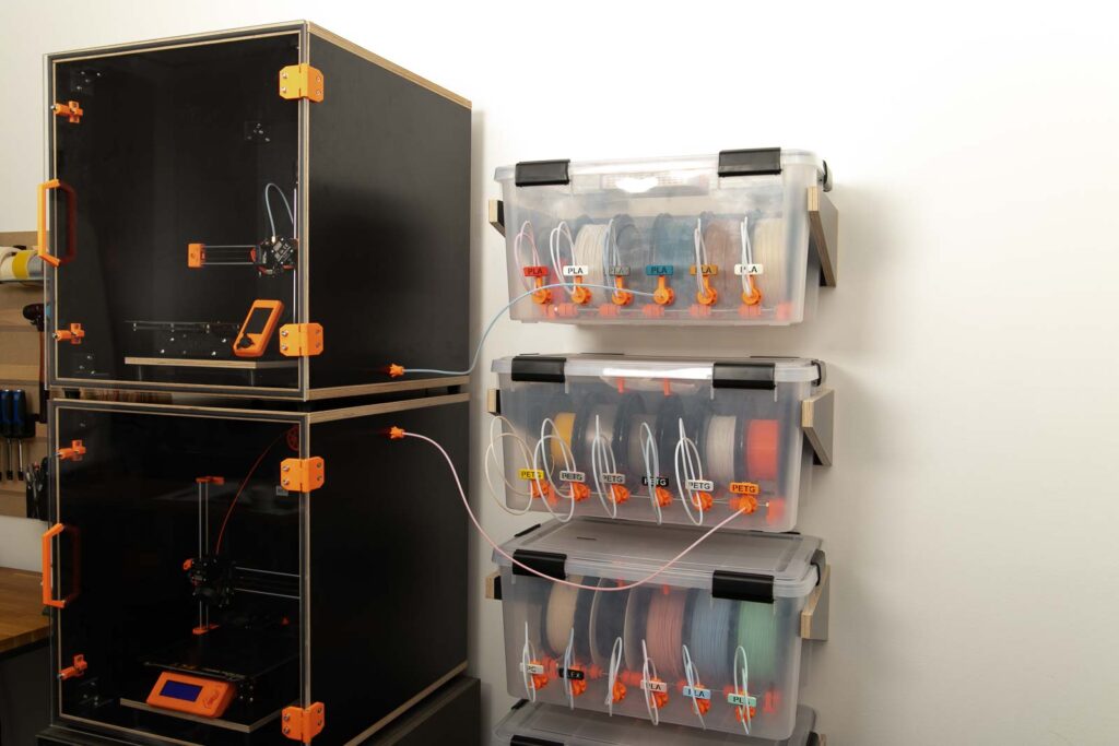
The tower of stacked filament boxes has reached a dangerous level and changing the spools becomes a logistical challenge? It doesn’t have to be, build the wall mounts for your filament dry boxes and save space and time.
Basically it’s very simple, you only need two tines at the right distance. Here you find the instructions to build a wall mount for your filament dry box.
You can find the instructions for building the filament dry box here:
The article contains affiliate/advertising links, which are marked with an asterisk (*). If you make a purchase through these links, I may receive a commission at no additional cost to you.
Purchased parts
The dimensions used for the wall mount, which is build in these instructions are for the Iris 50L Airtight Box (Amazon.de DE)* which can be bought in Europe. For the 46.6 Qt air-tight box (Amazon.com US)* and 62.8 Qt air-tight box (Amazon.com US)* in the English instructions of the DIY filament dry box, I unfortunately got no dimensions up to now. But it’s quite easy to measure the needed dimensions, which is shown afterwards in the instructions. So if a different plastic box is used, the dimensions must be adjusted. Afterwards there is also a list for wall mount dimensions for different box types.
- 1 pc Wooden panel 590 x 150 mm multiplex thickness= 18 mm (approx. 3/4″) black (approx. 10 USD / pc) – plate dimensions for the Iris 50l airtight box
- 2 pcs Wooden panels 340 x 150 mm multiplex thickness= 18 mm (approx. 3/4″) black (approx. 6 USD / pc) – plate dimensions for the Iris 50l airtight box
- 4 pcs Wood screws #8 X 1-1/2″ (approx. 4×40 mm) flat head (Amazon.com US)* (approx. 14 USD / 100 pcs)
The panels were already ordered cut to size from auprotec.com, only the slanted cut of the tines was sawn later. Unfortunately, the black 18 mm multiplex panels are currently not available at Auprotec.com. As an alternative there are plates available at Plattenzuschnitt24.de.
For mounting the bracket on the wall, two dowels and the matching screws and washers are also required for each wall mount. Make sure that they can support the weight of the holder and the fully loaded filament box without any problems.
- 2 pcs Dowels – suitable for the wall
- 2 pcs Screws – matching the dowels
- 2 pcs Flat washer DIN 125 M5 5.3x10x1 mm (Amazon.com US)* (approx. 7 USD / 100 pcs)
The total cost of the purchased parts comes to approximately 25 USD. Provided the wooden panels are ordered directly from auprotec.com, excluding shipping costs, and only the costs for the parts required for one wall mount are added together.
Alternative purchased parts
Similar wooden panels are also easily available cut to size at your hardware store of choice. Make sure that these are not too thin as the tines are screwed from behind. Do not go below the thickness of 18 mm (approx. 3/4″) here. If thicker plates are used, be sure to adjust the width of the base plate so that the distance between the tines is correct.
Screws, dowels and washers can usually be bought at hardware stores at a significantly lower price and, above all, in exactly the quantities required.
Tools used
- Jig saw (Amazon.com US)* or Plunge circular saw (Amazon.com US)*
- Cordless drill (Amazon.com US)*
- Screwdriver bit set (Amazon.com US)*
- Sandpaper 240 Grit (Amazon.com US)* for deburring the plate edges
- Wood drill bit 2 mm (Amazon.com US)* for pre-drilling the wooden panels
- Wood drill set with drill bits 4 mm and 6 mm (Amazon.com US)*
- Countersink (Amazon.com US)*
Instructions to build a wall mount for the filament dry box
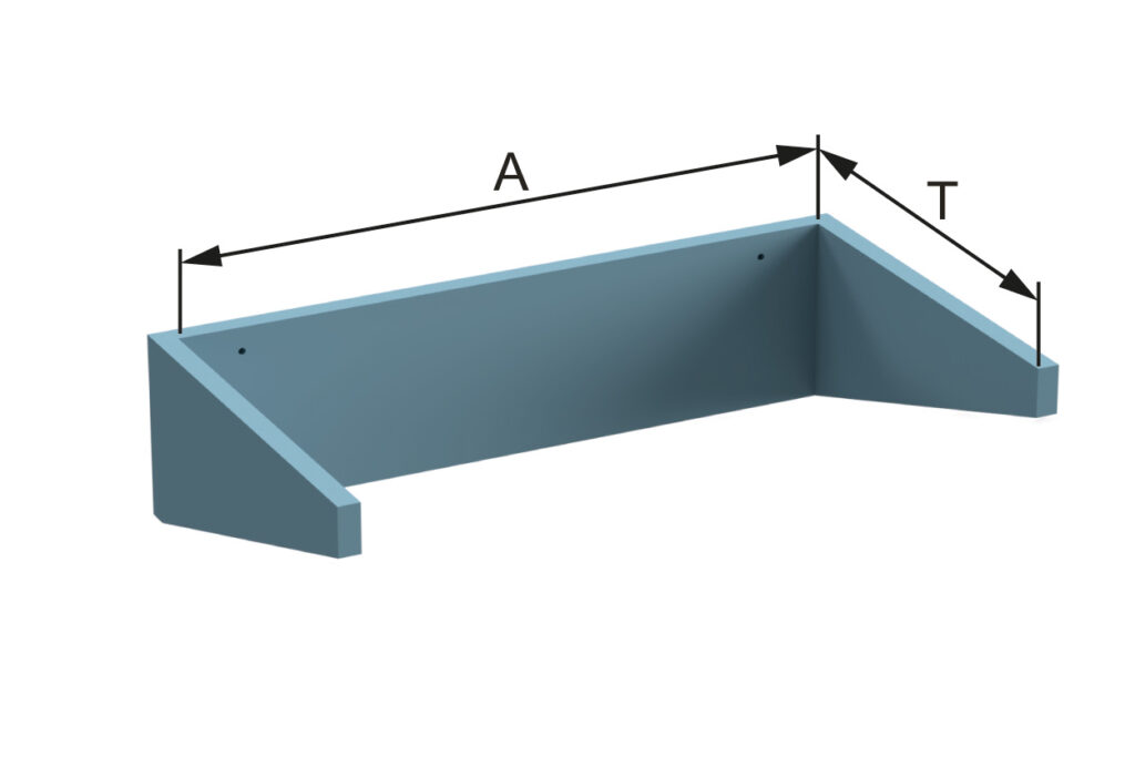
The most important thing when building the filament box holder is the distance between the tines A and the length of the tines T.
Depending on the box used, these dimensions are different, for a few boxes I have listed the dimensions here:
- 50L box from Iris (Amazon.de DE)* (shown in the filament box instructions German version) – Distance A= 554 mm and the tine length T= 340 mm
- IKEA US Samla Box 12 gallon or IKEA DE Samla Box 45L – Distance A= 532 mm and tine length T= 390 mm
- IKEA US Samla Box 6 gallon or IKEA DE Samla Box 22L – Distance A= 373 mm and tine length T= 280 mm
If you use a box other than those listed here, then measure the distance under the ribbing. Most plastic boxes have some kind of support bar there. Then add 2-3 mm additional clearance and you got the required tine distance A.
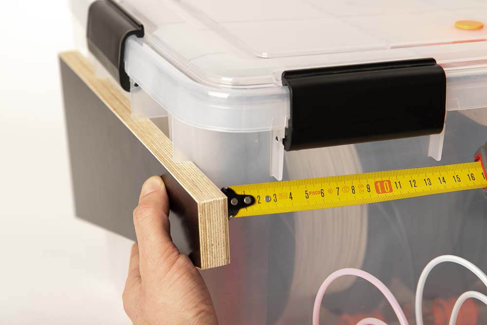
The easiest way to measure the distance is to hold two pieces of wood under the brims of the box. Then measure the distance using a tape measure. Don’t forget to add a few millimeters for clearance.
The length of the tines depends on the depth of the box or where the last load-bearing rib can rest on a tine. To do this, place the box against a wall at the back and measure with a tape measure from the wall to the last load-bearing rib. Don’t forget to allow for a few centimeters of protrusion to the front.
Have you used a box that is not yet represented here? Then please send me the measured distances to support@3d-druck-vorlagen.de. I’m going to list them here and make them accessible to everyone else.
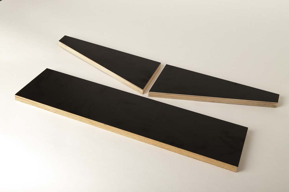
To build the wall mounts, I chose 18 mm multiplex (plywood) panels in black so that they visually match the DIY 3D printer enclosure.
Do you also want to build a 3D printed enclosure? Then click here for the instructions:
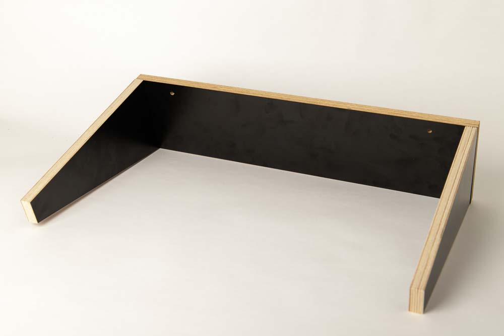
Three wooden panels are required for each holder, two tines and one base plate. The tines are screwed to the base plate from behind.
The width of the base plate results from the required tine distance plus 2 x plate thickness. In this case 554 mm tine spacing + 2 x 18 mm = 590 mm width.
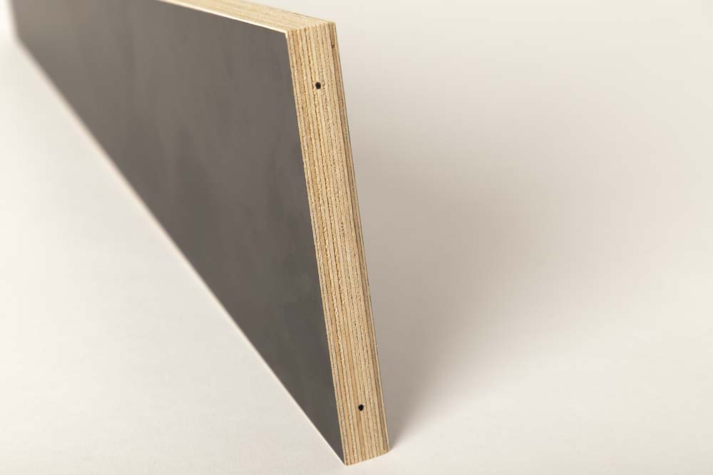
The tines were beveled using a circular saw; this can also be done using a jigsaw. The bevel is not absolutely necessary, just an optical detail.
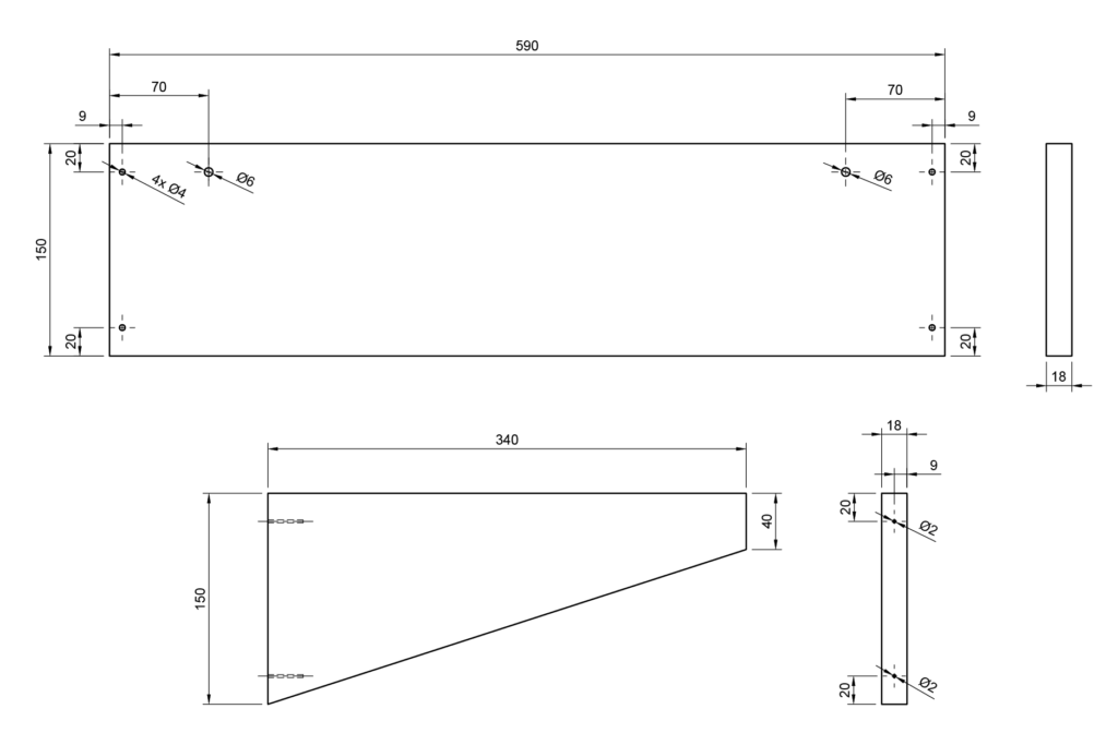
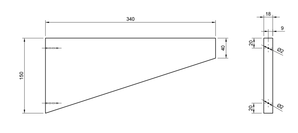
All dimensions are indicated on the technical drawing of the base plate and the tine.
If you use panels with a different thickness, the width of the base plate is calculated from the tine distance A + 2 x panel thickness. Then place the four 4 mm diameter holes for the tines in the middle of the plate = thickness / 2 instead of 9 mm. The same with the 2 mm pilot holes in the tine, place them in the middle of the panel = thickness / 2.
Safety Guidelines
Safety first! Read and follow the assembly instructions!
Read the entire assembly instructions carefully and follow the instructions and safety warnings. If something is unclear, simply contact the support (support@3d-druck-vorlagen.de).
These instructions are only intended for persons of legal age (over 18 years old). If you lack knowledge in handling the tools or processes that occur, then it is essential to seek the help of trained persons. The preparation and assembly of the project is at your own risk.
Legend: Warnings and symbols


General safety instructions for assembling the project
Wear protective goggles to protect your eyes during all processing steps that can produce chips (sawing, drilling).
Wear assembly gloves to protect your hands during all processing steps in which saws or knives are used. Do not wear gloves when drilling, there is a risk of being drawn into the drill.
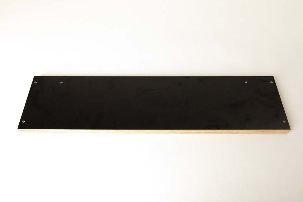
Step 1: Preparing the base plate
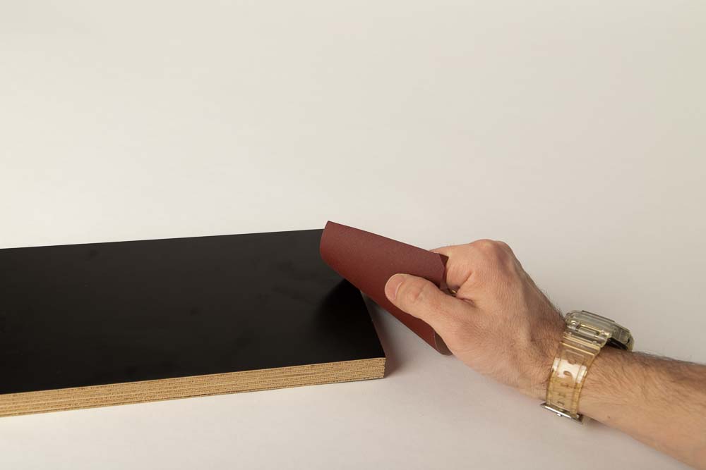
Deburr the edges of the base plate by using sandpaper.
Then the holes are made for the tine fixation and the attachment to the wall. The bores for the tines are set at half the thickness of the plate. In this case at 18 mm / 2 = 9 mm, see the technical drawing.
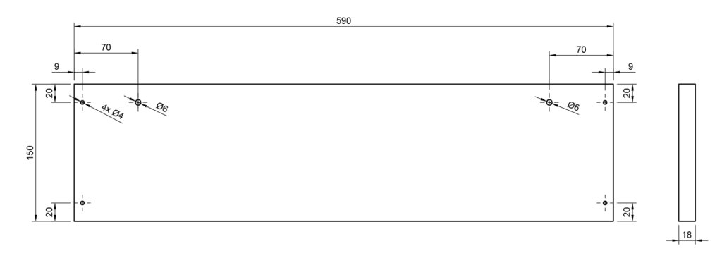
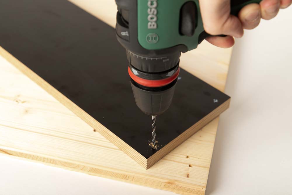
Bores with a diameter of 4 mm are drilled for the wood screws used.
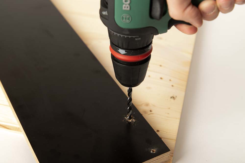
To screw the wall mount onto the wall, 6 mm holes are drilled so that the bracket can be leveled later.
Tip: Place a piece of sacrificial wood underneath when drilling so that the base plate does not tear or fray when the drill comes out.
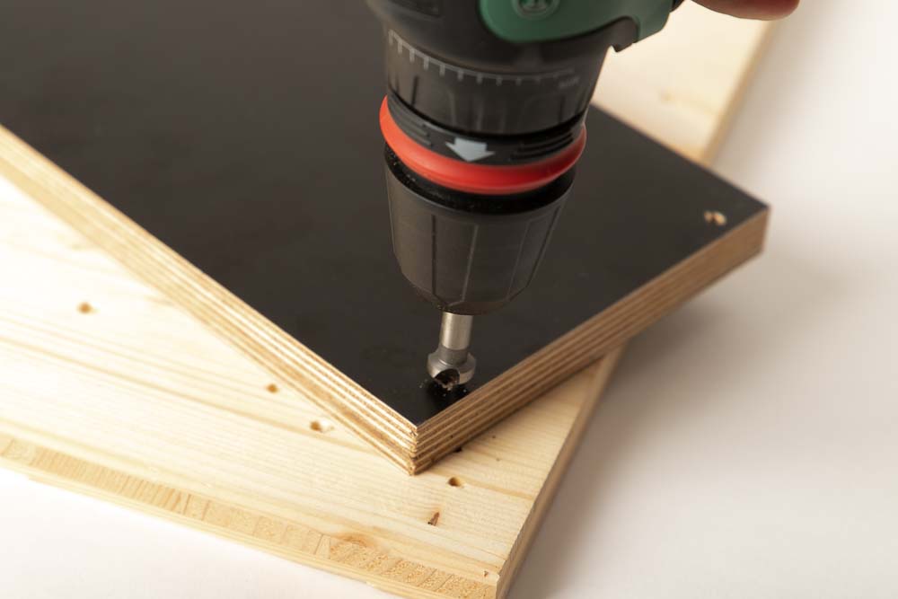
The 4 mm holes are then countersunk on the back of the base plate, so that the heads of the wood screws do not protrude later.
Step 2: Preparing the Tines
Remove sharp edges from the panels using sandpaper.
To ensure that the wood screws do not split the tines, 2 mm pilot holes are drilled. Place these with the distance selected for the base plate from the edge (20 mm) and in the middle of the plate thickness (9 mm).
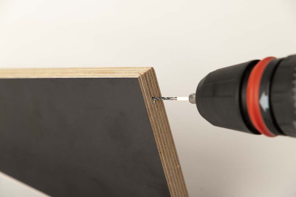
Make sure that the hole is drilled at a right angle to the surface. Pre-drill approximately 25 mm deep. It is best to mark the distance on the drill bit with adhesive tape before.
Step 3: Assembling the plates
Once all parts have been prepared, the tines are now screwed to the base plate.
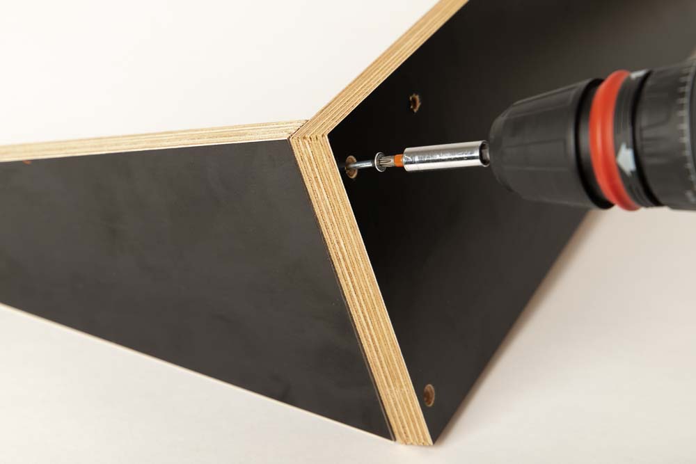
Insert the 4×40 mm (#8 X 1-1/2″) wood screws from the later back of the base plate, where the bores were prepared with the countersink. Find the pilot holes on the tines and screw them on there. Make sure that the holes for wall mounting the bracket are on the top (with a short distance to the top edge).
Screw the wood screws completely into the lowered cones of the base plate, so that they do not touch the wall later.
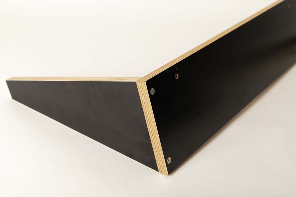
Screw on the tines on both sides and the filament dry box holder is ready.
Step 4: Mount the filament box holder on the wall
Now all that is left is to mount it on the wall.
Since the filament dry boxes protrude relatively far from the wall, the moment exerts a large force on the screws and dowels used. Therefore, make sure that screws and dowels are generously sized and that the filament box wall mount is tested with load after assembly.
Place the holes in the wall horizontally and at a distance of 450 mm (590 mm – 2x 70 mm for this version of the wall mount). Insert dowels that are suitable for the wall. Select the screws that match the dowels and base plate thickness.
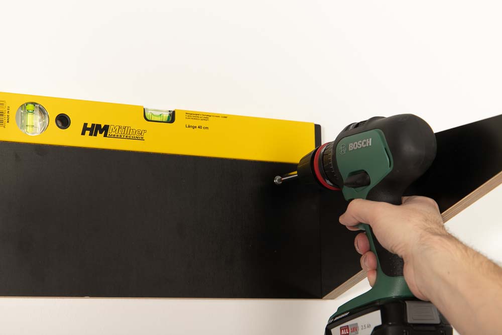
Place washers between the screws and the base plate of the wall mount, then the holder can be moved a little and leveled before final attachment.
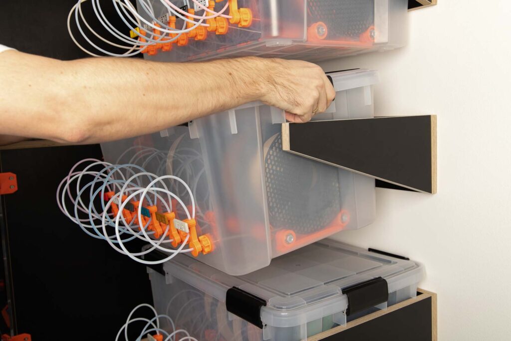
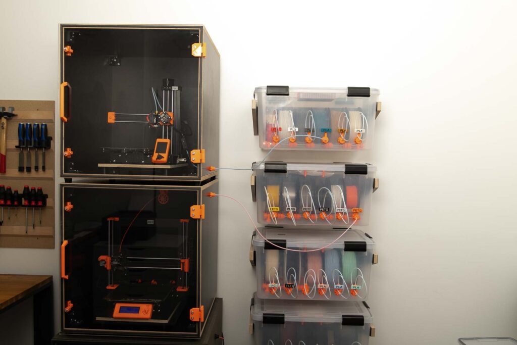
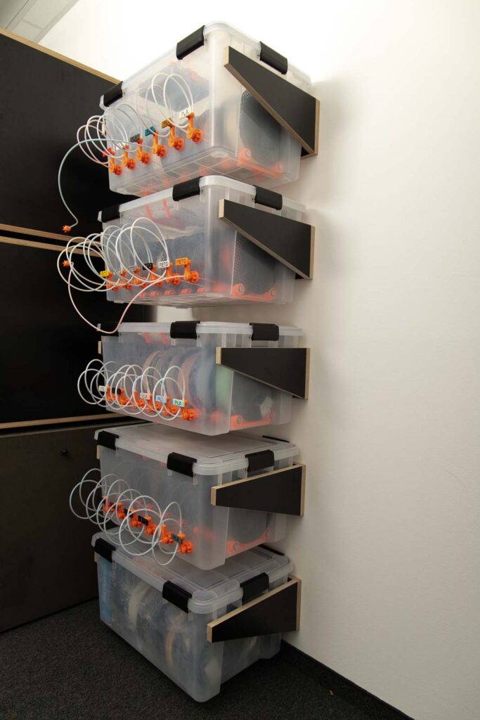
Done! Congratulations on your wall mount for your filament dry box! Untidiness in your 3D printing lab is now a thing of the past 😉
Now some photos how the wall mounts, filament dry boxes and the 3D printer enclosures look like in combination.
Disclaimer
The instructions and the associated files are an inspiration of Ingenieurbüro Dr. Janko GmbH to build this project yourself. Since Ingenieurbüro Dr. Janko GmbH has no way of checking and influencing the required quality of the printed components and purchased parts as well as the quality of the assembly and the correct functioning of the project or if any inadmissible changes and modifications to the project has been made, Ingenieurbüro Dr. Janko GmbH accepts no liability for functionality, stability or the damage incurred by the project.
0 Comments