

Does the buzzing and beeping of your 3D printer bother you? Are you tired of dust constantly soiling the guides of your 3D printer? Annoyed of the smell of some filaments? Do you want uniform ambient temperature to minimize warping of your 3D printed parts?
➔ Then it’s time to build a 3D printer enclosure!
Read here how a DIY 3D printer enclosure helps you with 3D printing and the best part is: use your 3D printer to print many parts for it yourself. These assembly instructions describe in detail which purchased parts you need and how you assemble your 3D printer box.
The article contains affiliate links/advertising links, these are marked with an asterisk (*). If you make a purchase through these links, I may receive a commission at no additional cost to you.
Why build a DIY 3D printer enclosure?
Almost all commercially available desktop FDM / FFF 3D printers are in open design. This has the advantage that they can be produced very cheaply and are easily accessible for repairs and upgrades. However, this also has the disadvantage that a surrounding enclosure is missing which helps you with some annoying issues.
3D printer too loud – a enclosure can help here!
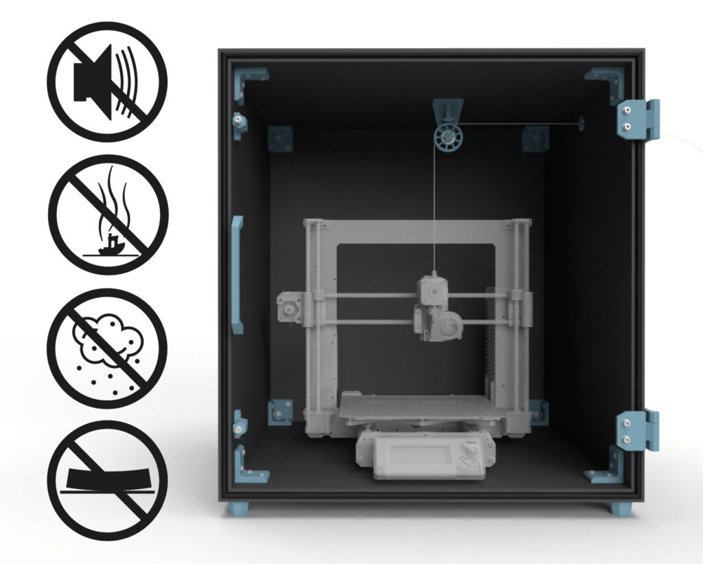
You can easily build such a 3D printer enclosure yourself and it will help you to reduce the volume of the 3D printer and the odors and vapors produced during 3D printing. The closed 3D printer box also keeps your printer dust-free.
Another advantage of a 3D printer enclosure is the higher and more stable ambient temperature. This improves the printing result and reduces the distortion (warping) of the printed parts.
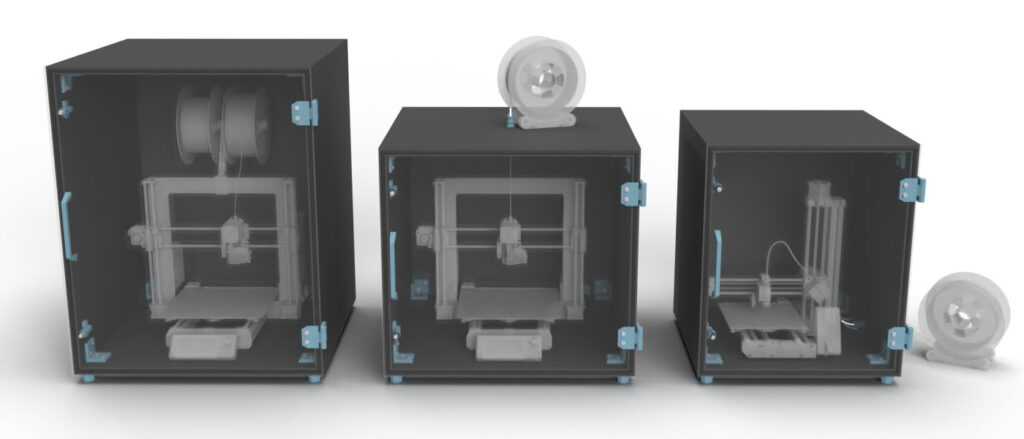
Build an individual 3D printer enclosure for your 3D printing setup
Design the 3D printer enclosure exactly as you need it, for a large or small 3D printer, with filament spools in the enclosure or with external filament feeding.
So, you can build the 3D printer enclosure tailor-made for your 3D print setup.
Now there are already many similar projects, for example the well-known solution of a DIY enclosure based on the IKEA Lack table and some acrylic sheets. The disadvantage of this 3D printer cabinet is the lack of stability and tightness of the enclosure. This is going to be noticeable in higher noise and exhaust emissions. Also, the IKEA based case has fixed dimensions and is not adaptable to your needs.
The here shown DIY enclosure was designed to get rid of these disadvantages. It is extremely stable, seals very well, consists of a few standardized purchased parts and is versatile and completely customizable thanks to the large number of 3D print files included.
Build a DIY 3D printer box yourself
You want to build this 3D printer enclosure, these highlights await you:
Fully customizable
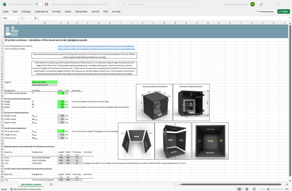
The tailor-made enclosure for your 3D printer. Simply enter the required dimensions of the enclosure and the wooden panel thickness using an Excel sheet. It then provides all the dimensions for cutting the panels to size.
Magnetic door lock
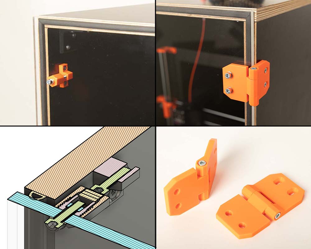
The magnetic door lock, the robust hinges and the sealing strip ensure that the door can be opened and closed very easily with very good noise and emission protection.
Filament feedthrough
Do you want to feed the filament in the enclosure from the outside – no problem. The 3D print files of the DIY 3D printer enclosure contain various solutions for this. From a simple implementation using a fixed PFTE tube up to a direct connection to your DIY filament dry box. Thanks to the included STL files for an internal filament guiding system with pulley, the filament can also be redirected inside the cabinet.
Easy cable feedthrough

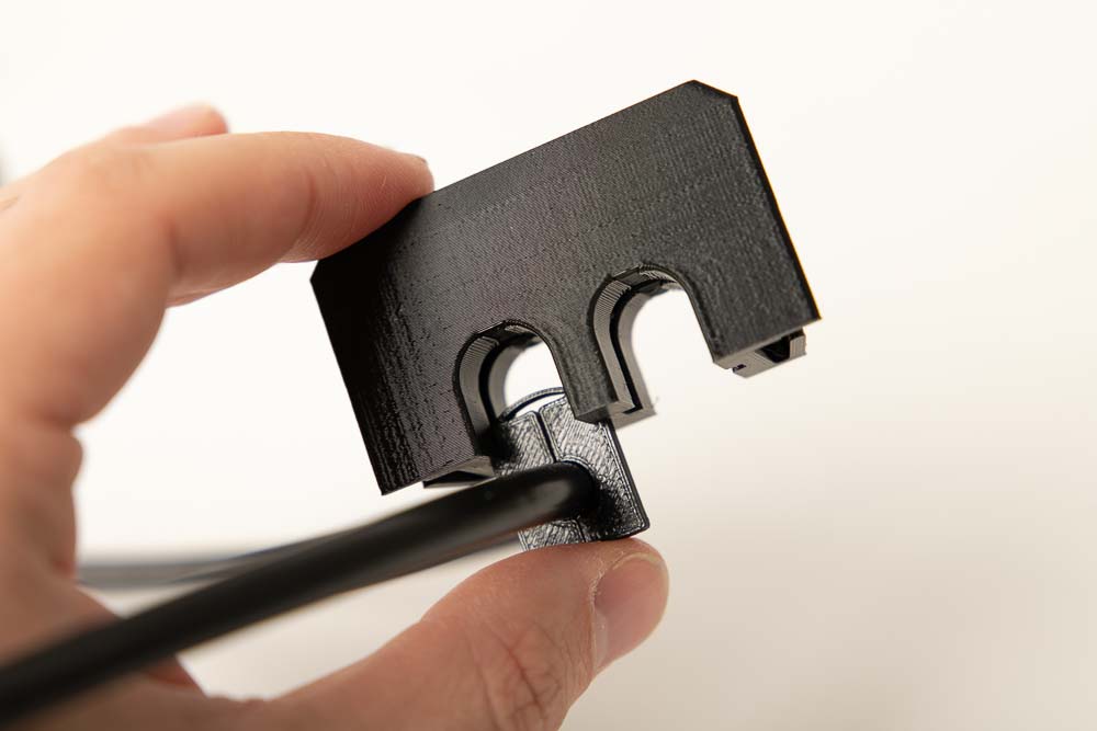
In addition to the power supply for your 3D printer, you may also want other things such as lights, sensors, or fans inside the 3D printer box. In order to route the necessary cables into the enclosure, there are two slots for all sort of cables per cable entry box. The various inserts cover almost every standard circular and rectangular cable cross-section.
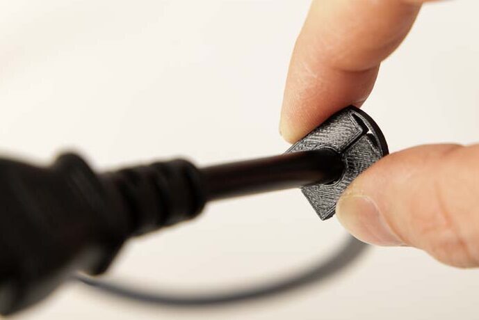
Simply print the appropriate insert for your cable, clip it on the cable and slide them into the cable entry box. The cable entry box is then pushed into the 3D printer enclosure.
The instructions are divided into individual steps:
- You already read a short overview, followed by
- the 3D print parts,
- the 3D print settings,
- the bill of materials, and
- the recommended tools for this DIY project.
- This is followed by the detailed assembly instructions.
3D print parts
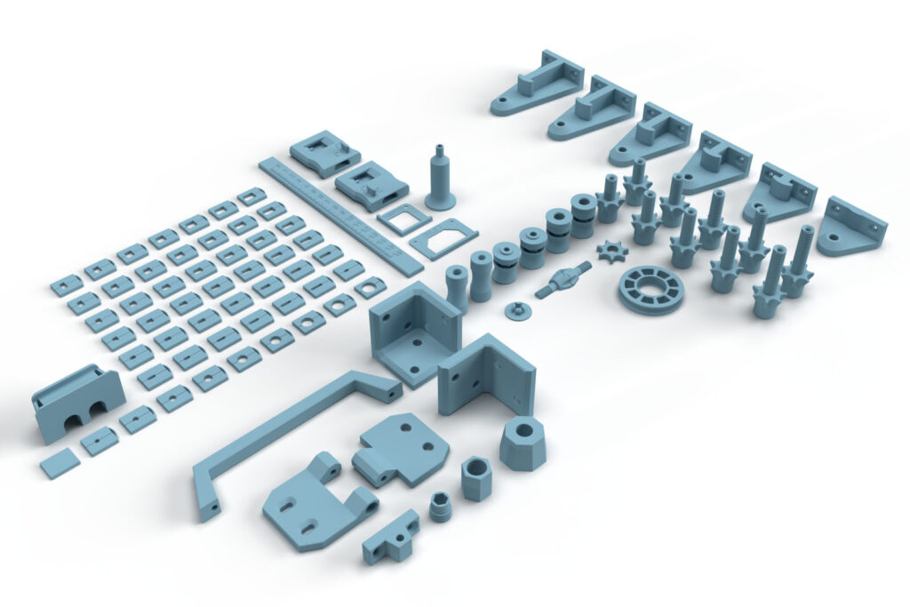
These are purely digital products, you get all the files you need to print the parts yourself in a ZIP folder. It contains the STL files for all required components and variants, additional accessories, as well as templates and installation aids. A total of 97 different 3D print models are included.
- 002300_Pulley
- 002400_Screw
- 002900_Bracket_3-sided
- 003000_Bracket_2-sided
- 003100_Handle
- 003200_Hinge_Part_1
- 003300_Hinge_Part_2
- 003400_Magnetic_Lock_Screw_Holder
- 003500_Magnetic_Lock_Magnet_Holder
- 003600_Magnetic_Lock_Cap
- 003700_Supporting_Foot
- 003800_Cable_Entry_Box
- 003900_Cable_Entry_Insert_closed
- 004000_Cable_Entry_Insert_Bore_D##
9 models with bore diameters D= 3, 4, 5, 6, 7, 8, 9, 10, 11 mm - 004100_Cable_Entry_Insert_Rectangular_W#_L##
42 models of all combinations of rectangular slots with width W= 2, 3, 4, 5, 6, 7 mm and length L= 4, 5, 6, 7, 8, 9, 10 mm - 004200_Pulley_Holder_A##
6 models with distances A= 10, 20, 30, 40, 50, 60 mm - 004300_Inlet_Tube_Connector_OD#_L##
10 models of all combinations of attachable PTFE tube diameter outside OD= 4, 5 mm and length of the carrying-through L= 20, 25, 30, 35, 40 mm - 004400_Inlet_Nut
- 004500_Bore_Cover
- 004600_Tube_Clamp_OD4
- 004600_Tube_Clamp_OD5
- 004700_Tube_Clamp_with_Thread_OD4
- 004700_Tube_Clamp_with_Thread_OD5
- 004800_Tube_Coupling_OD4
- 004800_Tube_Coupling_OD5
- 004900_Marker
- 005000_Stencil_Cable_Entry_Box
- 005100_Stencil_Stand
- 005400_Ruler
- 005500_Lock_Left
- 005600_Lock_Right
- 000400_Tool_Bearing_Press_In
- 000500_Tool_Bearing_Press_Out
- 000600_Tool_Bearing_Press_Counter
The largest 3D printed part of this project (003100_Handle) requires a footprint (X,Y) of 170 x 40 mm, the highest part (004300_Inlet_Tube_Connector_OD#_L40) is 61 mm high (Z). Any 3D printer with a build space (X, Y, Z) of at least 170 x 170 x 70 mm is suitable for this project.
Do you already have a 3D printer enclosure and only need the filament feedthroughs and the pulley? By popular demand, the files are now also available to buy individually: 3D print files of the DIY filament feedthroughs with pulley
3D printing settings
For the 3D print part 004200_Pulley_Holder_A##:
- Layer height 0.2 mm and 20% infill (rectangular)
All other 3D printed components:
- Layer height 0.2 mm and 100% infill (rectangular)
The following settings have proven useful for the PETG Filament* used:
- Nozzle temperature: 250°C (First layer: 240°C)
- Bed temperature: 90°C (First layer: 85°C)
- Perimeter speed: 45 mm/s (First layer: 10 mm/s)
- External and short perimeter speed: 25 mm/s (First layer: 10 mm/s)
- Infill speed: 80 mm/s (First layer: 10 mm/s)
- Top solid infill speed: 40 mm/s
Used 3D printing filament and 3D printer
3D printer used: Prusa i3 MK3s* with a standard 0.4 mm nozzle.
3D printing filament used: In this guide, Prusament PETG Prusa Orange* and Prusament PETG Jet Black*, as well as Prusament PETG Urban Gray were used for the auxiliary tools. The feet can be printed from PETG, or to further reduce vibration and noise emissions from flexible filament. The flexible Fiberlogy Fiberflex 30D Black* was used for this.
With the selected settings, approx. 600 g of filament is used to 3D printing the parts of the 3D printer box.
With the PETG filament used (29.90 EUR/kg), the filament material costs are approx. 18 EUR per 3D printed enclosure.
The total printing time for all required components is approx. 50 hours. To calculate the total printing time, all printing times are added together, with the entire quantity of a component being printed at once.
Because of the higher stability and the low distortion, I recommend a filament made of PETG. The parts can also be printed with ABS or ASA, but these place higher demands on the 3D printer and operator. The widely used PLA is not recommended, because technically more demanding parts are not stable enough due to the more brittle nature of this material and the lower layer adhesion.
Bill of materials: Needed purchased parts to build the 3D printer enclosure
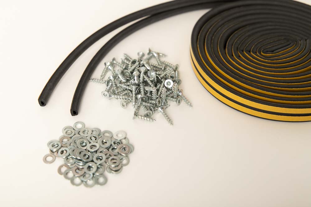
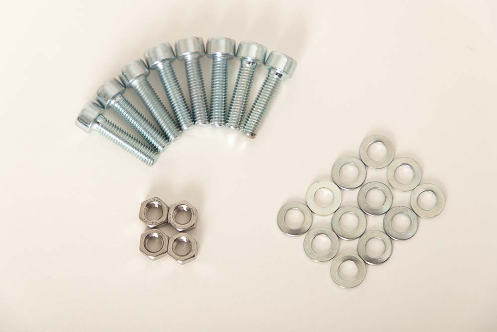
In addition to the wooden and acrylic / plexiglass panels, screws, nuts, and other smaller purchased parts are also required.
Panels needed
The 3D printer enclosure can be completely adjusted to your 3D printer. To calculate the required plate dimensions, you can download an Excel calculation sheet here. The calculation sheet is of course also included in the 3D print files of the DIY 3D printer enclosure.
If you want to build exactly the 3D printer box that is shown in this guide, then the Excel file is already pre-filled. For example, this case fits the Prusa i3 MK3s without a spool holder (with external filament feed).
When planning the enclosure, it is very important to give the printer enough space, paying close attention to all moving parts and cables of the printer. The cables must not touch the enclosure walls or rub against them. Plan enough space for filament rolls placed later in the enclosure or for the filament feedthrough and, if necessary, a filament redirection pulley. Also consider enough space for any LED lights, damper feet or damper boards that may be used. The best way to do this, is to set up the desired 3D printer setting, drive through all extreme positions of the 3D printer and determine the maximum displacements. Add a few centimeters of safety to the found maximum dimensions to get the required internal dimensions of the 3D printer enclosure.
To build the 3D printer enclosure shown here, the following panels were used:
- 2 pcs of wooden panels for Base and Top 580 x 580 mm plywood thickness = 18 mm black (approx. 38 USD / pc)
- 2 pcs of wooden panels for Left and Right 580 x 580 mm plywood thickness = 18 mm black (approx. 38 USD / pc)
- 1 pc of wooden panel for Rear 579 x 543 mm plywood thickness = 18 mm black (approx. 36 USD)
- 1 pc acrylic panel for the Door 616 x 580 mm Plexiglas GS (cast) thickness = 8 mm (approx. 47 USD)
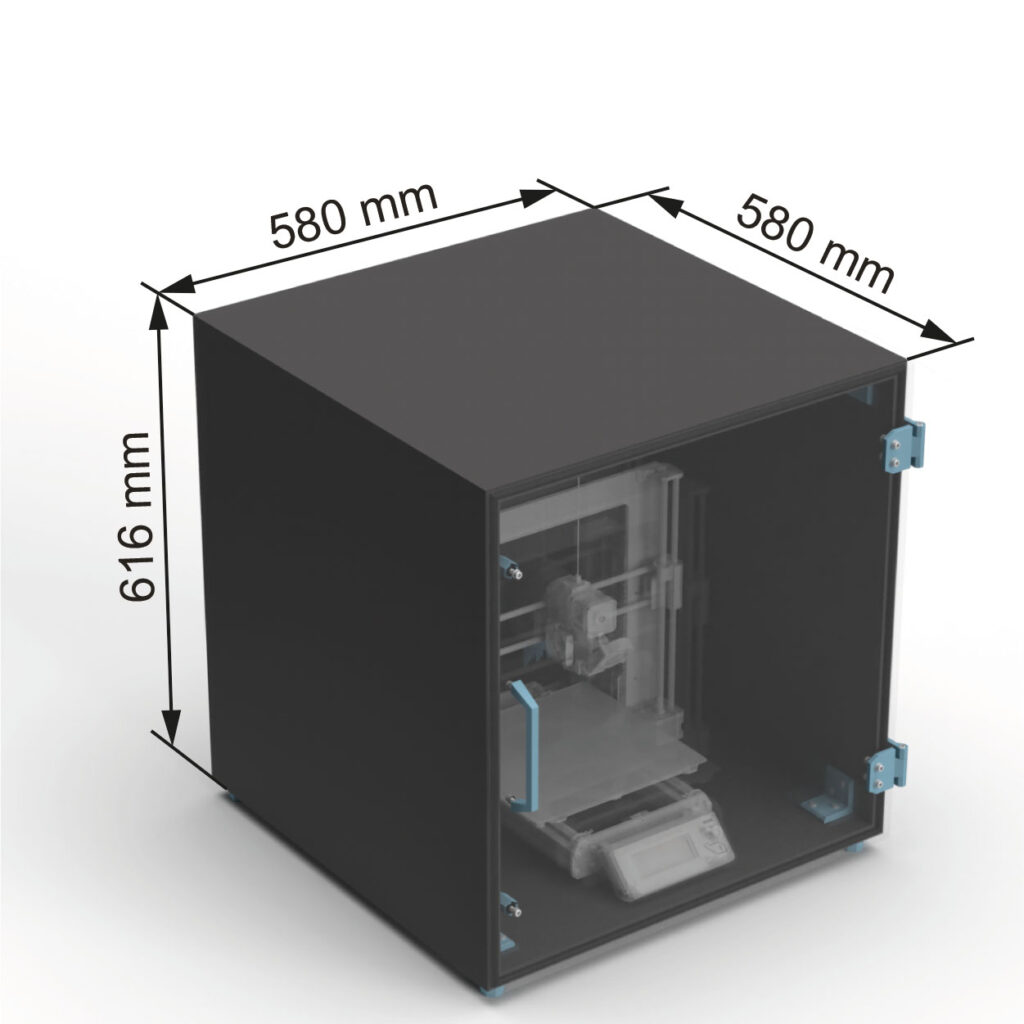
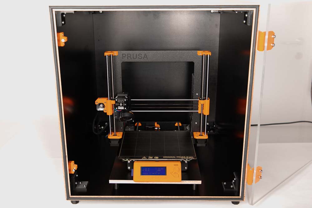
The 3D printer enclosure built here in the instructions has the external dimensions of 58 x 61.6 x 58 cm (W x H x D). It offers plenty of space for your 3D printer, as shown here, a Prusa i3 MK3s without a spool holder.
In this version, the filament comes from outside of the box. If the filament spools should be in the enclosure, and sit on the 3D printer, then the enclosure must be dimensioned higher.
There are many online shops for cut-to-size wood and acrylic panels, the panels installed here in this instructions were bought from auprotec.com (plywood panels / Multiplex) and kunststoffplattenonline.de (acrylic panel / Plexiglass). Cast (GS) is recommended for the acrylic / Plexiglas, extruded acrylic / Plexiglas (XT) has more internal stresses and is not recommended for the necessary processing steps (drilling). Setting the through bores there could cause cracks. Unfortunately, the black 18 mm multiplex plywood panels are currently not available at Auprotec.com. As an alternative there are plates available at Plattenzuschnitt24.de.
The thickness of the panels can be varied, the 3D print models included in their various variants have been designed for this. Wooden panels that are between 12 mm and 35 mm thick can be used. The 18 mm version shown here has been tested and has proven. When using thinner or thicker wooden panels, it is essential to ensure that the appropriate wood screws are used, shorter or longer than the 4×20 wood screws recommended here for the 18 mm version. And of course, the 3D printer enclosure must also be checked for stability before use. It is recommended to use wooden panels with less than 18 mm thickness only for very small boxes.
Theoretically, a thinner plate could also be chosen for the acrylic door. However, this can mean that it is too flexible, and the door does not close and seal properly. If this occurs, additional magnetic locks can be used to close the door tightly, for example an additional lock at the top and bottom.
With the M5x20 mm cylinder head screws, Plexiglas / acrylic plates from 5 to 8 mm can be used, with different panel thicknesses screws with different lengths must be selected.
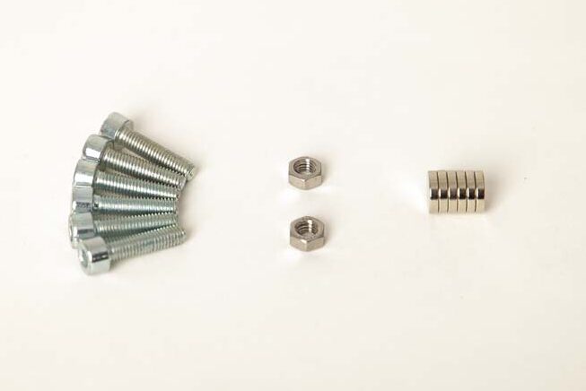
Smaller purchased parts
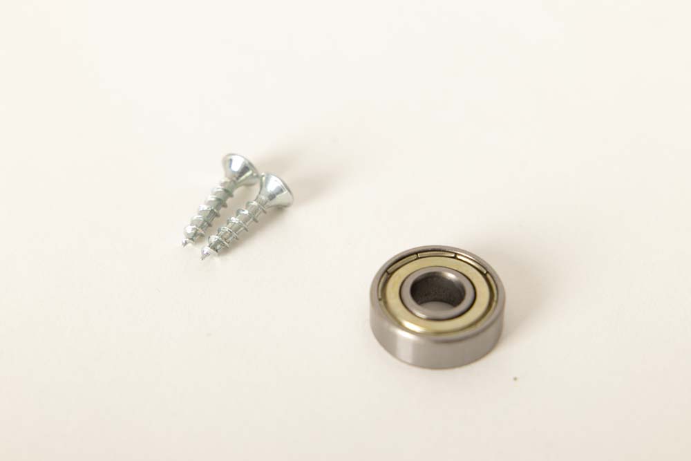
- 54 pcs Wood screws #7 x 3/4″ flat head (corresp. 4×20 mm) (Amazon.com US)* (approx. 9 USD / 100 pcs)
- 56 pcs Flat washer DIN125 M5 5.3x10x1 mm (Amazon.com US)* (approx. 7 USD / 100 pcs)
- 6 pcs Hex nut M5 (Amazon.com US)* (approx. 7 USD / 100 pcs)
- 14 pcs Socket head cap screws M5x20 mm DIN 912 / ISO 4762 – 12.9 black oxide (Amazon.com US)* (approx. 10 USD / 50 pcs) – must be normal steel! Do not use stainless steel (A2 or A4) screws as they are not magnetic enough to hold the magnetic lock.
- 6 pcs Magnets Neodym 10×2 mm (Amazon.com US)* (approx. 12 USD / 100 pcs)
- approx. 4 m (13 ft) Sealing tape D-type 9×6 mm 10 m (33 ft) (Amazon.com US)* (approx. 8 USD / 10 m) – the exact length is the circumference of the door
Optional for special filament feedthrough variants, see Step 10: Filament feedthroughs
- approx. 15 cm (0.5 ft) PTFE tube ID3 OD4 (Amazon.com US)* (approx. 9 USD / 3 m) – alternatives: OD5 ID3 or OD5 ID4 PTFE tube
- 1 pc Ball bearing 608 (Amazon.com US)* (approx. 9 USD / 20 pcs) – if the redirection pulley is used to guide the filament
The panels come to about 235 USD (at auprotec.com and kunststoffplattenonline.de)
The smaller purchased parts come to about 16 USD (via Amazon.com)
The total cost of the purchased parts comes to around 251 USD, without shipping costs and if only the costs for the parts required for a 3D printer enclosure are added up.
If cheaper wooden panels are used, the costs for the purchased parts of the 3D printer enclosure can also be reduced to below 140 USD, see alternative purchased parts.
Alternative purchased parts
Panels, sealing tape, screws, washers, and nuts: These are usually much cheaper in a hardware store and sometimes can be bought in the required quantity.
Cheaper wooden panels: The wooden panels used here in the assembly instructions are coated panels, similar (but uncoated) are also available much cheaper. For example, direct cutting at a hardware store, where the wooden plywood panels 18 mm (without coating) cost a total of only approx. 75 USD. This means that all purchased parts together come to less than 140 USD.
Steel brackets: The wooden panels of the 3D printer enclosure are held together by 3D printed brackets, to be robust they are very thick and are printed with 100% infill, which requires a lot of filament and printing time. Of course, it is also possible to use standard steel brackets from the hardware store.
Feet: If additional damping of the enclosure is desired, but you do not want to purchase extra flexible filament, you can also use rubber feet from the hardware store or these rubber supporting feet (Amazon.com US)*, for example. With these purchased parts, the correct fastening screw must then be selected. Pay particular attention and check the load limits of the purchased parts.
PTFE tubes: In addition to the tubes with OD4 ID3 (outer diameter 4 mm and inner diameter 3 mm), it is also possible to build the filament feedthroughs in the 3D printer box with OD5 ID3 or OD5 ID4 PTFE tubes. Always choose the inner diameter (ID) at least 1 mm larger than the filament diameter you want to use. This means using an ID3 PTFE tube for 1.75 mm filament and an ID4 PTFE tube for 2.85 mm filament.
Recommended tools
As always, a new project is the best excuse to buy new tools ;), not all are required but some help save some time.
- Cordless drill (Amazon.com US)*
- Screwdriver bit set (Amazon.com US)*
- Jig saw (Amazon.com US)*
- Jig saw blades – clean wood (Amazon.com US)* for clean cuts
- Sandpaper 240 Grit (Amazon.com US)* for breaking/deburring the panel edges
- HEX key set 1.5-10 mm (Amazon.com US)* including the 4 mm and 6 mm Allen keys
- Torx L-Key Set (Amazon.com US)* if using Torx wood scews
- Wrench set (Amazon.com US)* wrench for M5 nut (8 mm)
- Wood drill bit 2 mm (Amazon.com US)* for pre-drilling on the wooden panels
- Wood drill set with drill bits 3-12 mm (Amazon.com US)* 6 mm drill for the holes in the plexiglass plate, it is best to use a wood drill or even better a plastic drill / 10 mm for the power cable and filament feedthroughs
- Marker pen (Amazon.com US)*
- Box cutter (Amazon.com US)*
- Scissors (Amazon.com US)*
- Triangle ruler 45 degree angle – square (Amazon.com US)*
- Tape measure (Amazon.com US)*
- Super glue (Amazon.com US)*
- Bar clamps – long reach (Amazon.com US)*
- Mitutoyo vernier caliper (Amazon.com US)*
- Or alternatively digital caliper – Digital caliper (Amazon.com US)*
- Masking tape (Amazon.com US)*
- Bike chain lube (Amazon.com US)* to lubricate the door hinges
Assembly instructions: DIY 3D printer enclosure build
The assembly instructions for the 3D printer enclosure are divided into 11 steps, which you find in the following chapters:
- Step 1: Preparing the panels
- Step 2: Processing the wooden panels
- Step 3: Machining the acrylic panel
- Step 4: Preparing the magnetic locks, cable entry, and hinges
- Step 5: Assembling the 3D printer box
- Step 6: Assembling the acrylic door
- Step 7: Install and adjusting the door
- Step 8: Place the 3D printer in the enclosure
- Step 9: Determine the position for the filament feedthrough
- Step 10: Filament feedthroughs
- Step 11: Test run of the self-made 3D printer enclosure
Safety Guidelines
Safety first! Read and follow the assembly instructions and the operating manual!
Read the entire assembly instructions and operating manual carefully and follow the instructions and safety warnings. If anything is unclear, simply contact support (support@3d-druck-vorlagen.de).
These instructions are only intended for persons of legal age (over 18 years old). If you lack knowledge in handling the tools or processes that occur, then it is essential to seek the help of trained persons. The preparation and assembly of the project is at your own risk.
Warnings and Symbols


General safety instructions for assembling the project
Wear protective goggles to protect your eyes during all processing steps that can produce chips (sawing, drilling).
Wear assembly gloves to protect your hands during all processing steps in which saws or knives are used. Do not wear gloves when drilling, there is a risk of being drawn into the drill.
When printing parts, sharp edges can occur (usually on the first layer), there is a risk of cuts. These edges must be deburred.
Step 1: Preparing the panels
After the arrival of the ordered cut to size wooden panels and the acrylic panel, it is best to check the dimensions chosen for your project immediately. Then divide the panels as follows (resulting from the dimensions): Top, Base, Left, Right, Rear, and – of course easy to distinguish – the transparent Door.
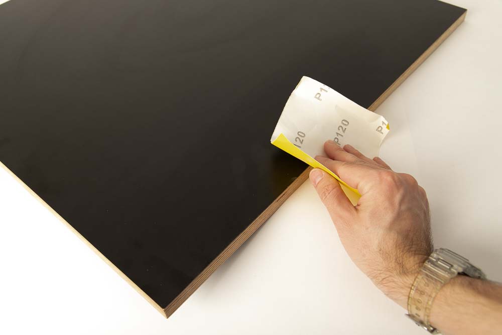
If the cut edges of the panels are very sharp, simply use some fine sandpaper and deburr them.
After sorting the panels, examine the faces and edges of the panels, decide which side should later face outwards and which side will face inwards, towards the 3D printer.
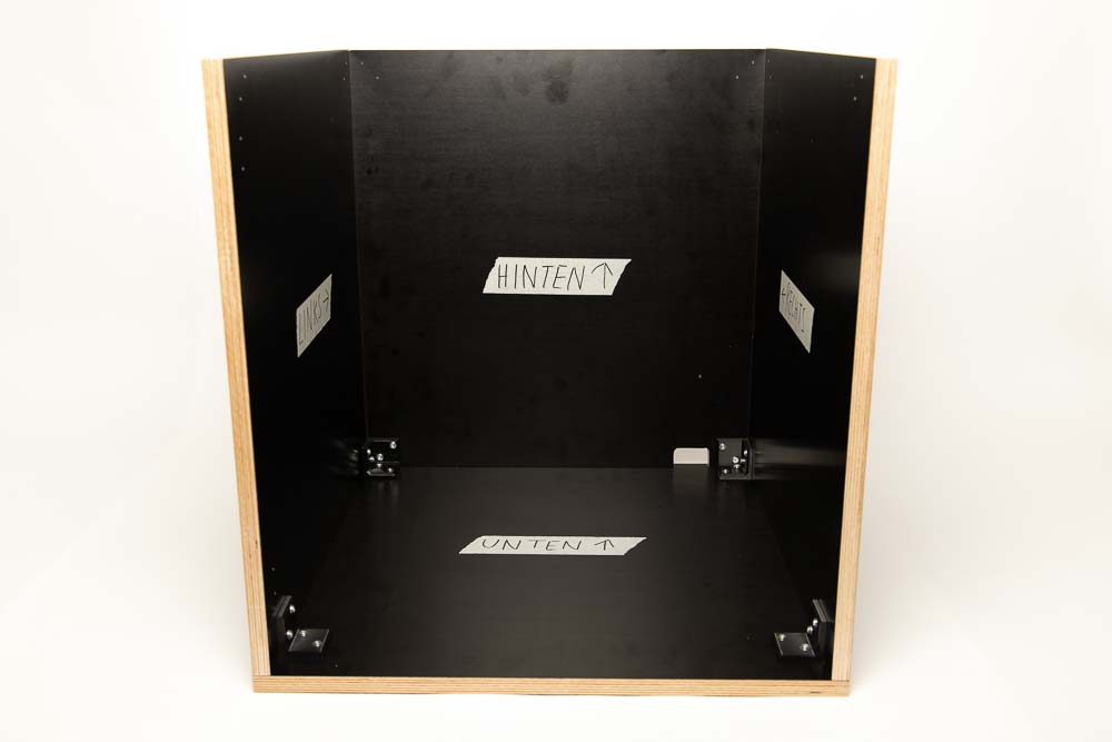
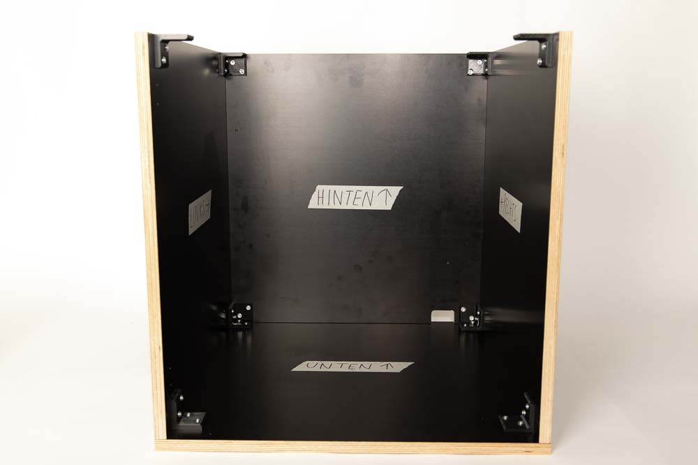
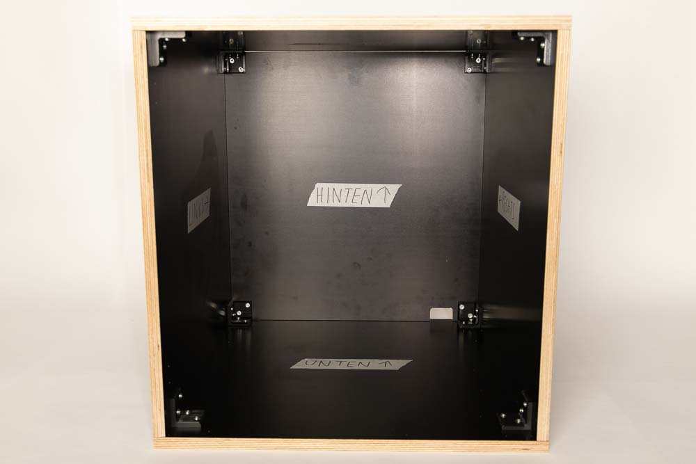
To identify the panels more easily during processing and to always orientate them correctly, attach painters or masking tape to the future inward-facing sides of the panels. Use the inscriptions and arrows shown in the figure below.
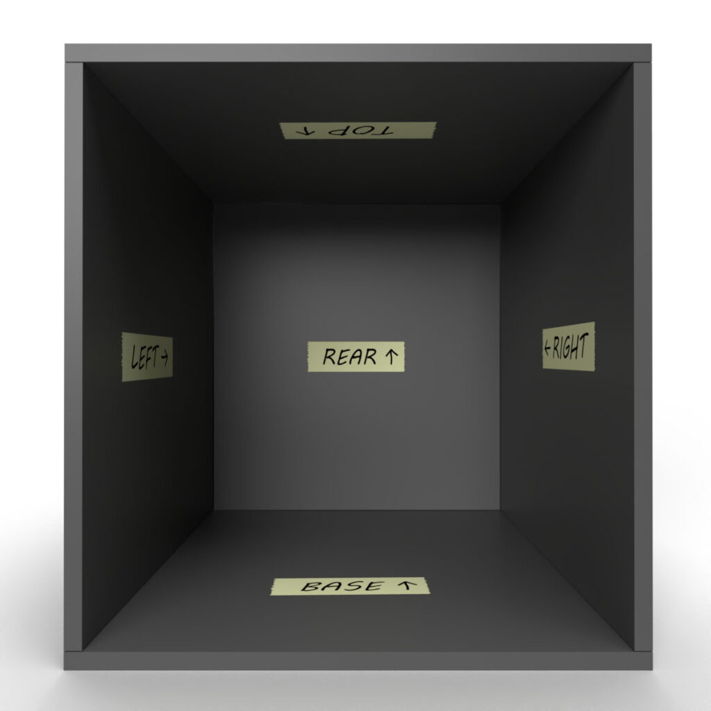
Important step to keep the overview: label the later inner sides of the panels, the arrows always point backwards towards the Rear panel. The arrow on the Rear panel points up.
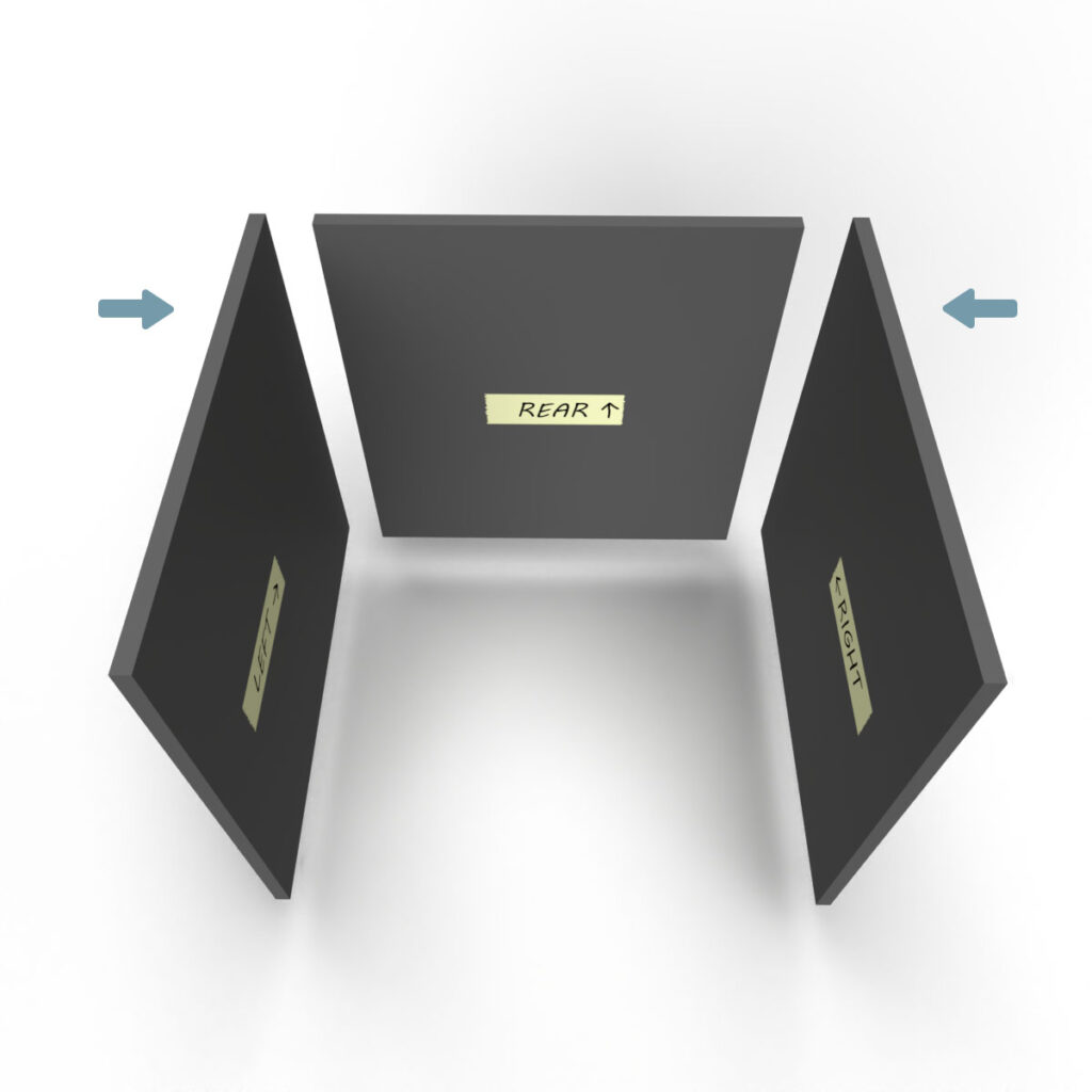
The wooden panels are later assembled as follows:
- The Rear panel is between the Left and Right panels.
- The Top and Base panels then close these three panels at the top and bottom.
- The Right, Left and Rear panels are sitting on the Base panel and are covered at the top with the Top panel.
This gives the 3D printer enclosure stability and so later several boxes can be stacked on top of each other.

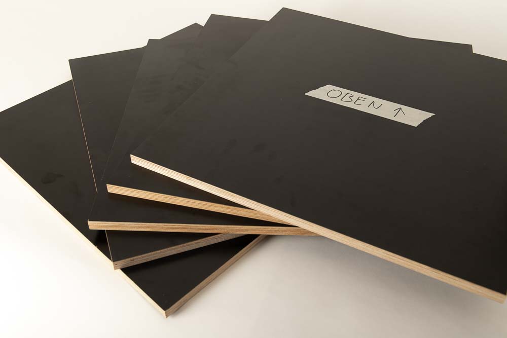
Prepared panels ready for the next step. The picture shows a label in German (Oben means Top)
Step 2: Processing the wooden panels
To make the assembly of the 3D printer enclosure easier, it is best to drill all the pilot holes first, before assembling. In addition to the 3D printed brackets that are now required, there are also a few handy tools that are included in the 3D print files of the DIY 3D printer enclosure.
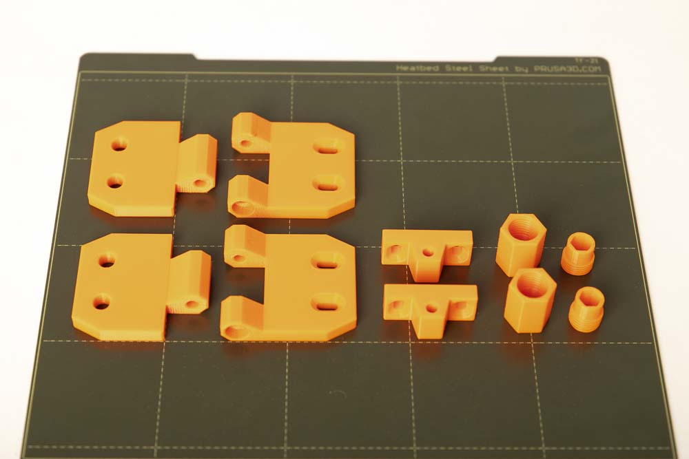
Required 3D printed parts
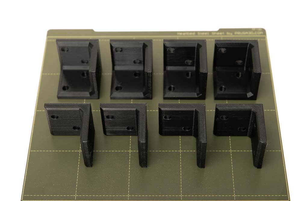
- 4 pcs 002900_Bracket_3-sided
- 4 pcs 003000_Bracket_2-sided
Layer height 0.2 mm and 100% infill (rectangular)
Be sure to print the Bracket_2-sided in the position as lying “L” as shown, so the stability is higher.
Be sure to print the brackets with 100% infill and a mechanically robust filament (e.g.: PETG, ABS, ASA).
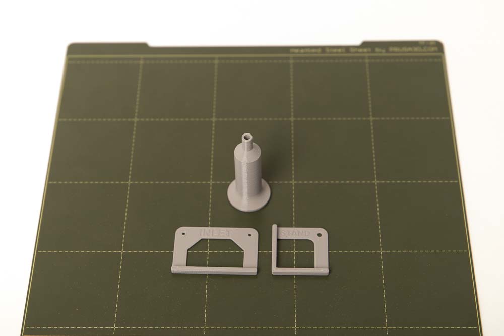
- 1 pc 004900_Marker
- 1 pc 005000_Stencil_Cable_Entry_Box
- 1 pc 005100_Stencil_Stand
Layer height 0.2 mm and 100% infill (rectangular)
The 3D print files of the DIY 3D printer enclosure also include the 3D print files of the depth caliper. These are a great help in positioning the brackets. The Assembly instructions of the 3D printed depth caliper can be found at the link.
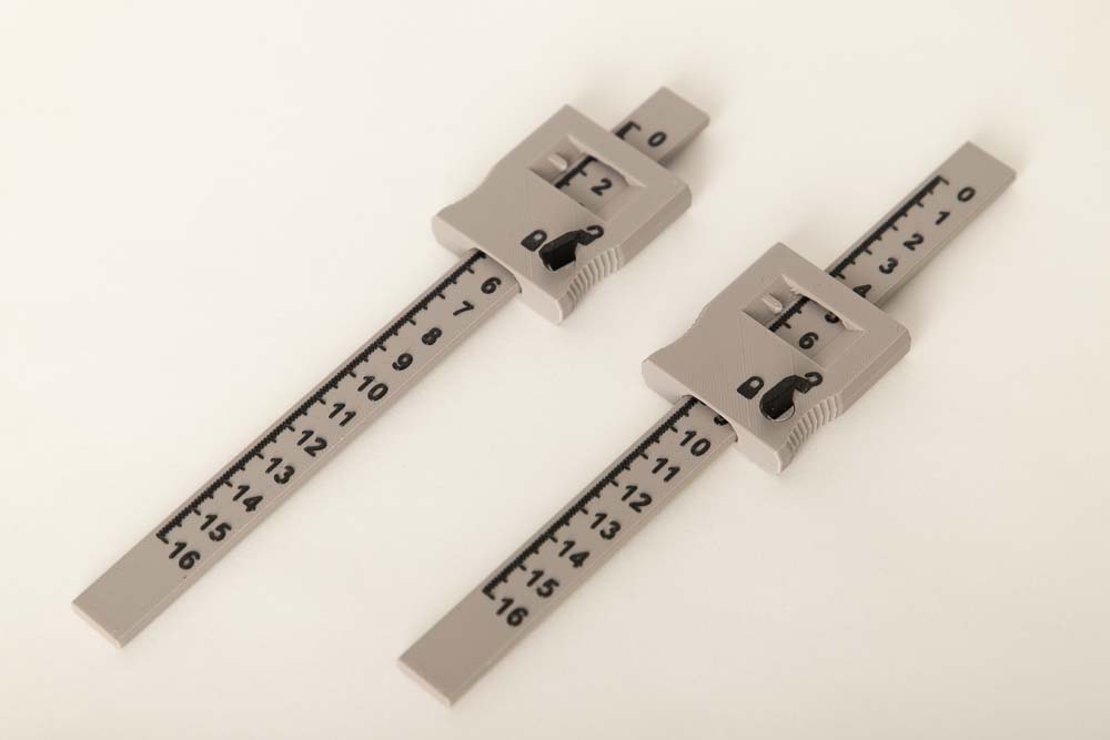
- 2 pcs 005400_Ruler
- 2 pcs 005600_Lock_Right
or 2 pieces 005500_Lock_Left depending on personal preference.
Layer height 0.2 mm and 50% infill (rectangular)
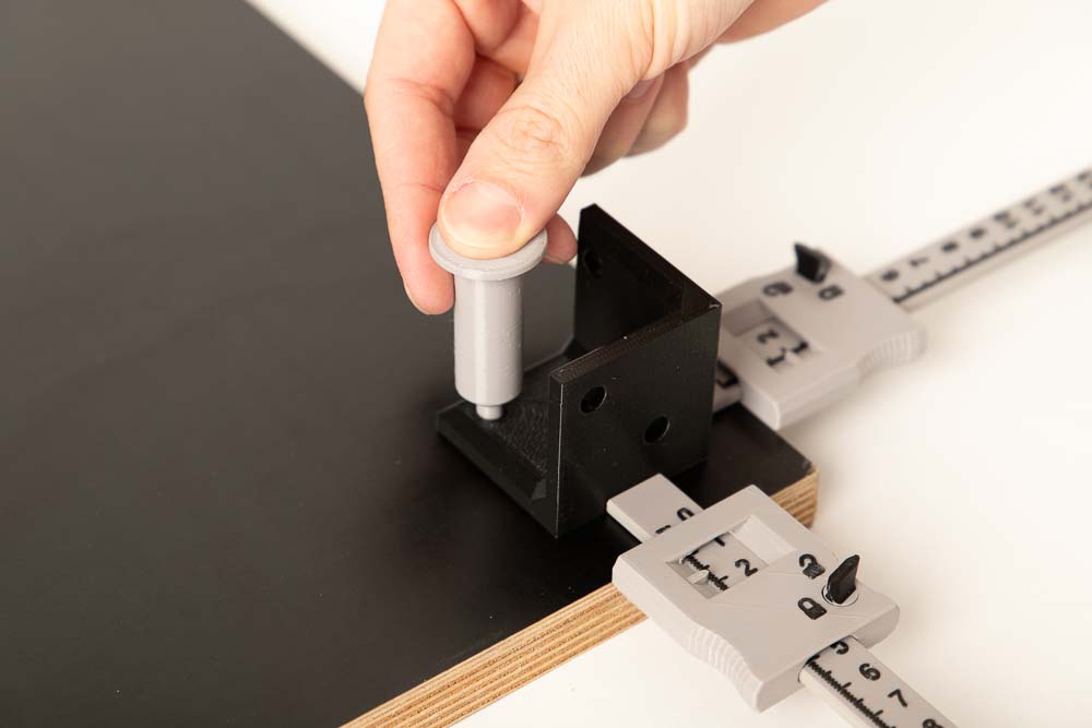
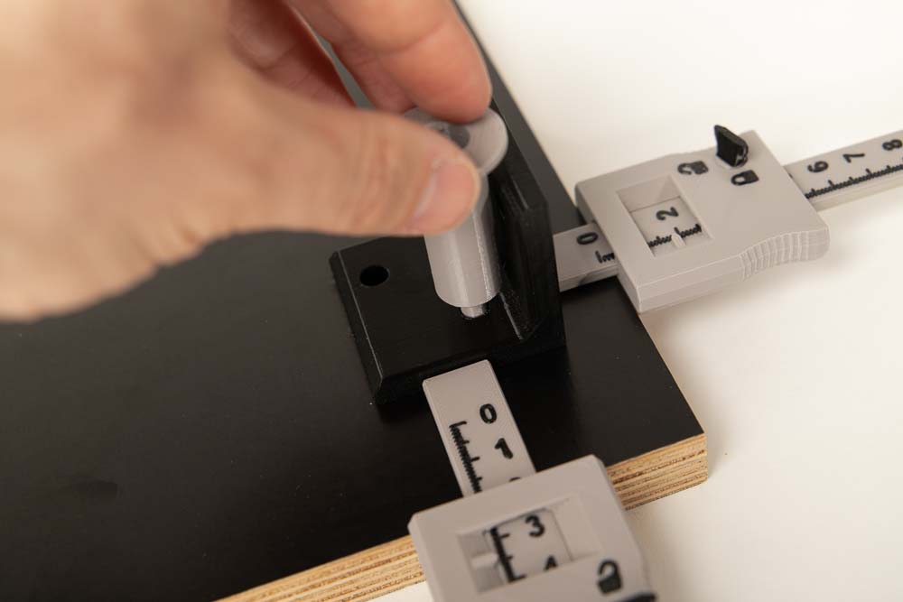
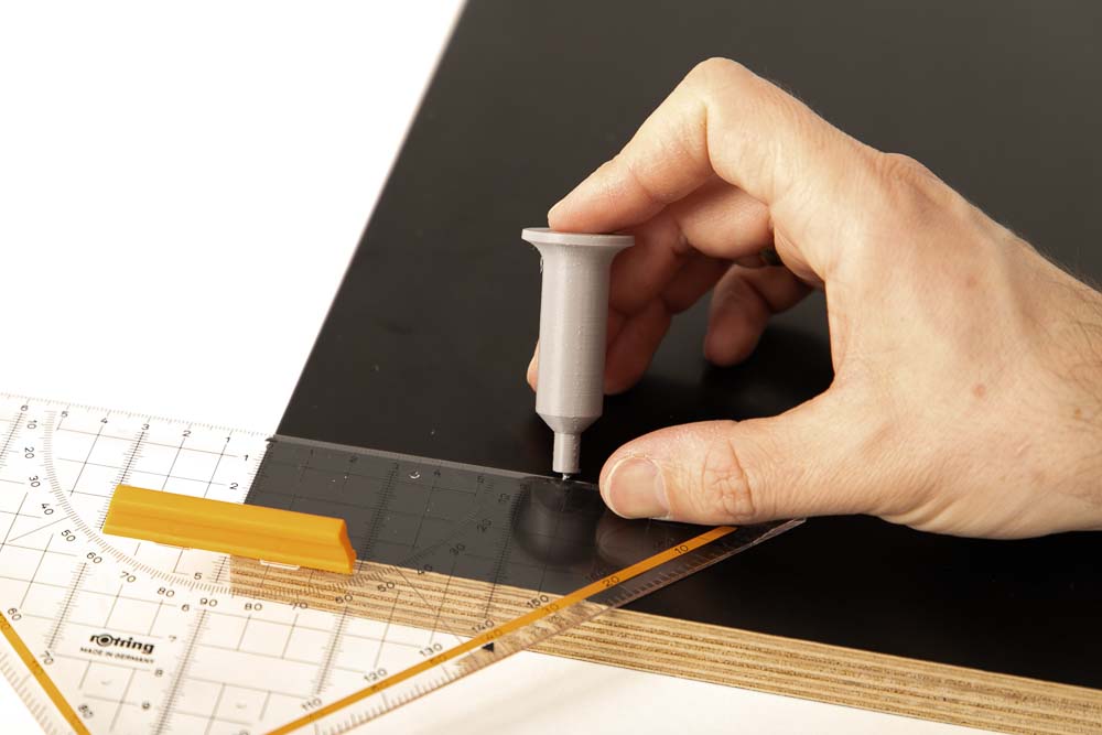
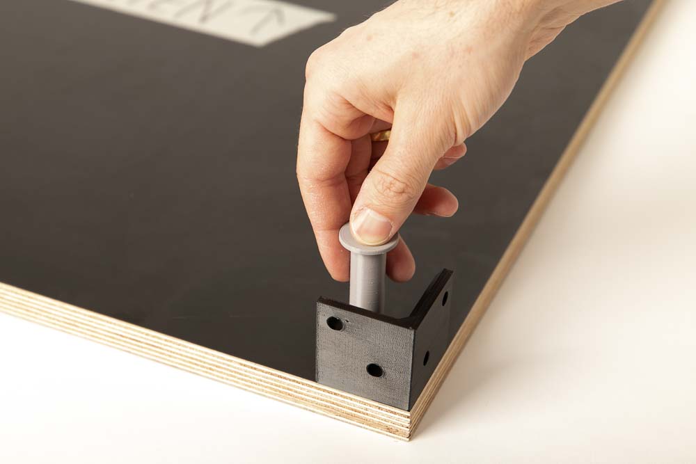
Preparation of the marker
With the help of the marker, the position of the pilot holes can be easily marked on the wood through the bracket-holes.
Screw one of the 4×20 mm wood screws through the 3D printed marker from behind so that the tip protrudes approx. 2-3 mm at the front. The marker is a kind of center punch that fits exactly into the holes in the printed brackets. By pushing the marker through the holes in the brackets, you mark the center of the needed pilot holes on the wooden panels.
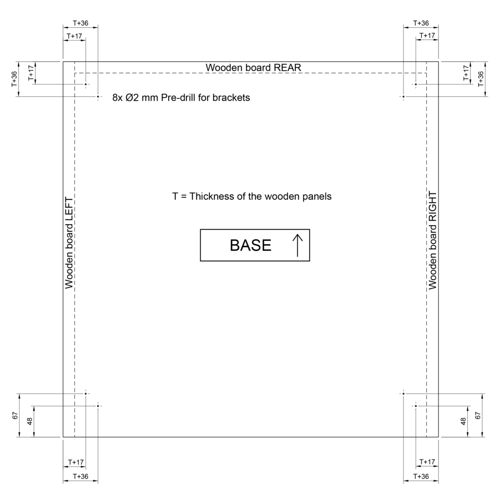
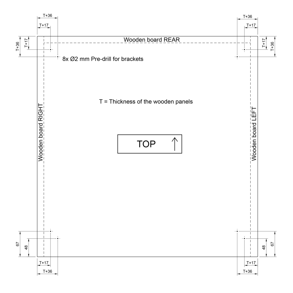
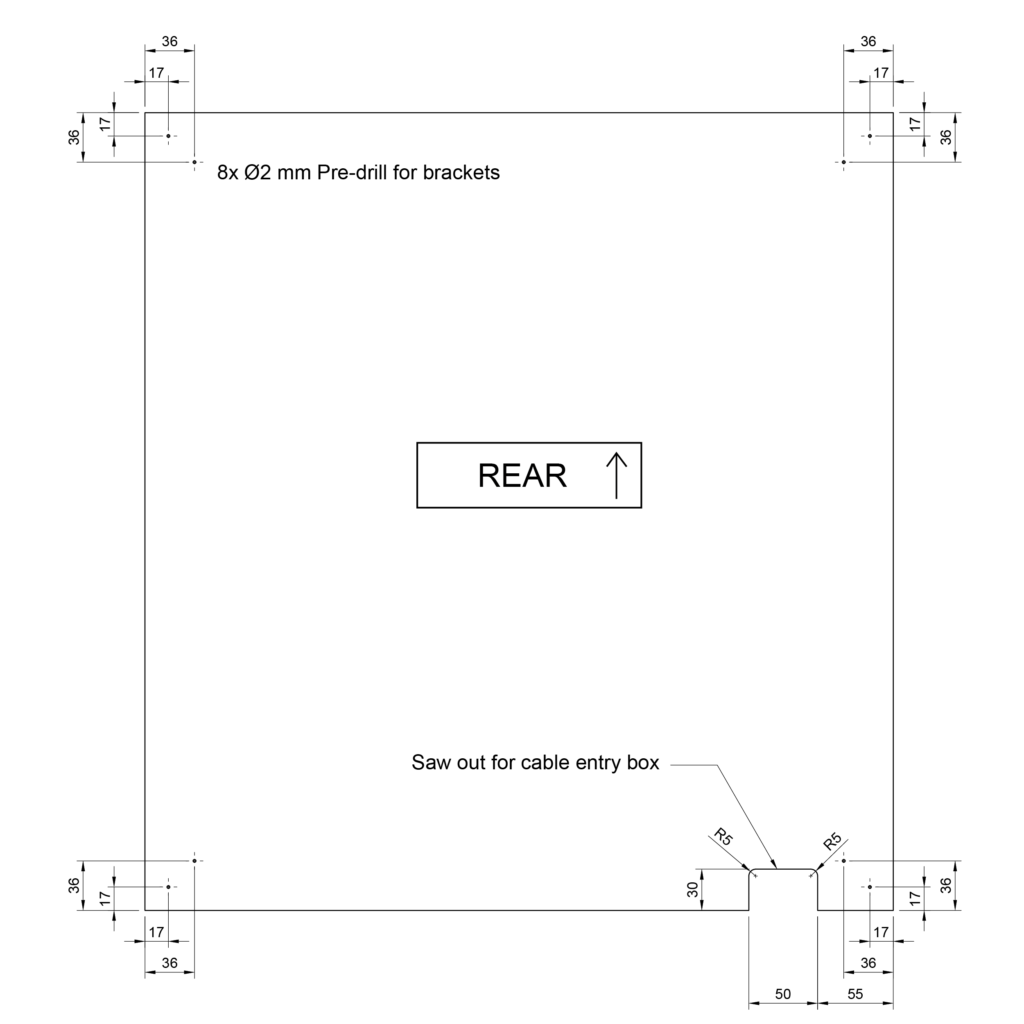
Base panel – mark and pre-drill for the brackets and supporting feet
The Left, Right and Rear panels are later placed on the Base panel. It is important here that the brackets and the pilot holes for them are offset inwards by the selected panel thickness T. For example, if the thickness is T = 18 mm, then the dimensions 18+17 = 35 mm and 18+36 = 54 mm are measured from the edge for the pilot holes at the back.
The supporting feet will also be screwed onto this panel. For this reason, four pre-drilled holes are prepared on the underside (later the outside).
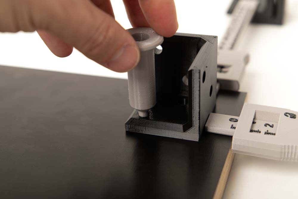
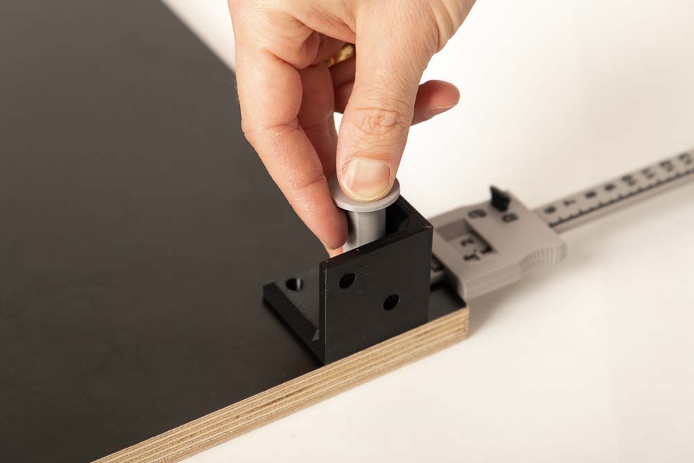
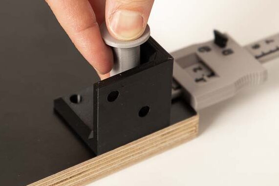
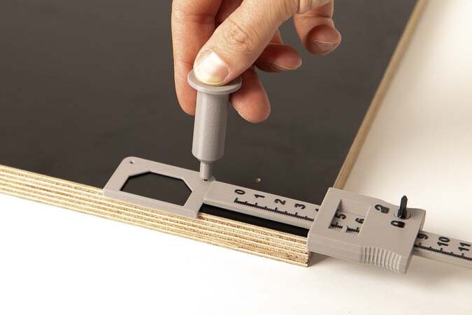
To save yourself a lot of measuring, all the necessary marks can also be set with the help of the brackets, the depth calipers, and the marker, see the following photo.
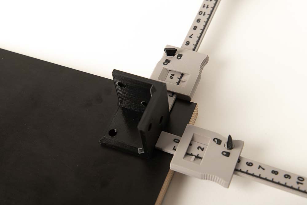
Rear pilot holes: Set the Bracket_3-sided here by the thickness of the wooden panels from the edges inwards. The Left, Right and Rear panels will sit there later.
Simply set the panel thickness – in this case 18 mm – on the depth gauge and fix it. Then position the bracket on the plate and hold it.
Use the marker to mark the pre-drilling holes on the panel through the two holes in the bracket.
Repeat on the left side of the panel.
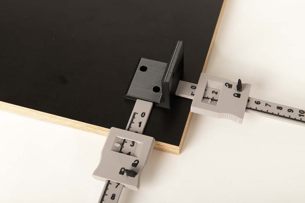
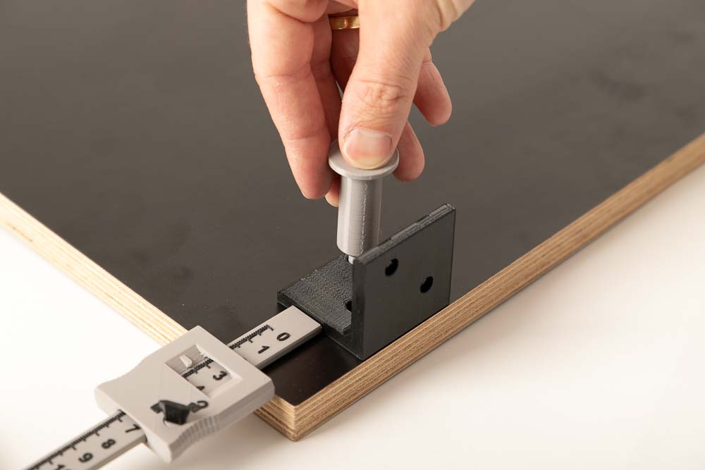
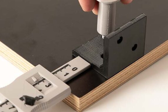
Front pilot holes: Place the 003000_Bracket_2-sided by the thickness of the wooden panels from the right edge inwards. The Right panel will sit there later.
Then set and fix 35 mm from the front on one of the depth gauges. Position the bracket on the plate and hold it.
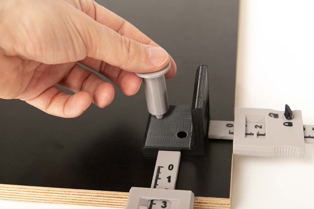
Use the 3D printed marker to mark the pilot holes on the panel through the two holes in the bracket.
Repeat on the left side of the panel.
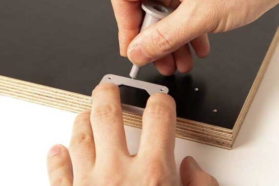
On the later outside (side without masking tape), four pilot holes are set for the supporting feet. Super easy with the included STL file for the stencil.
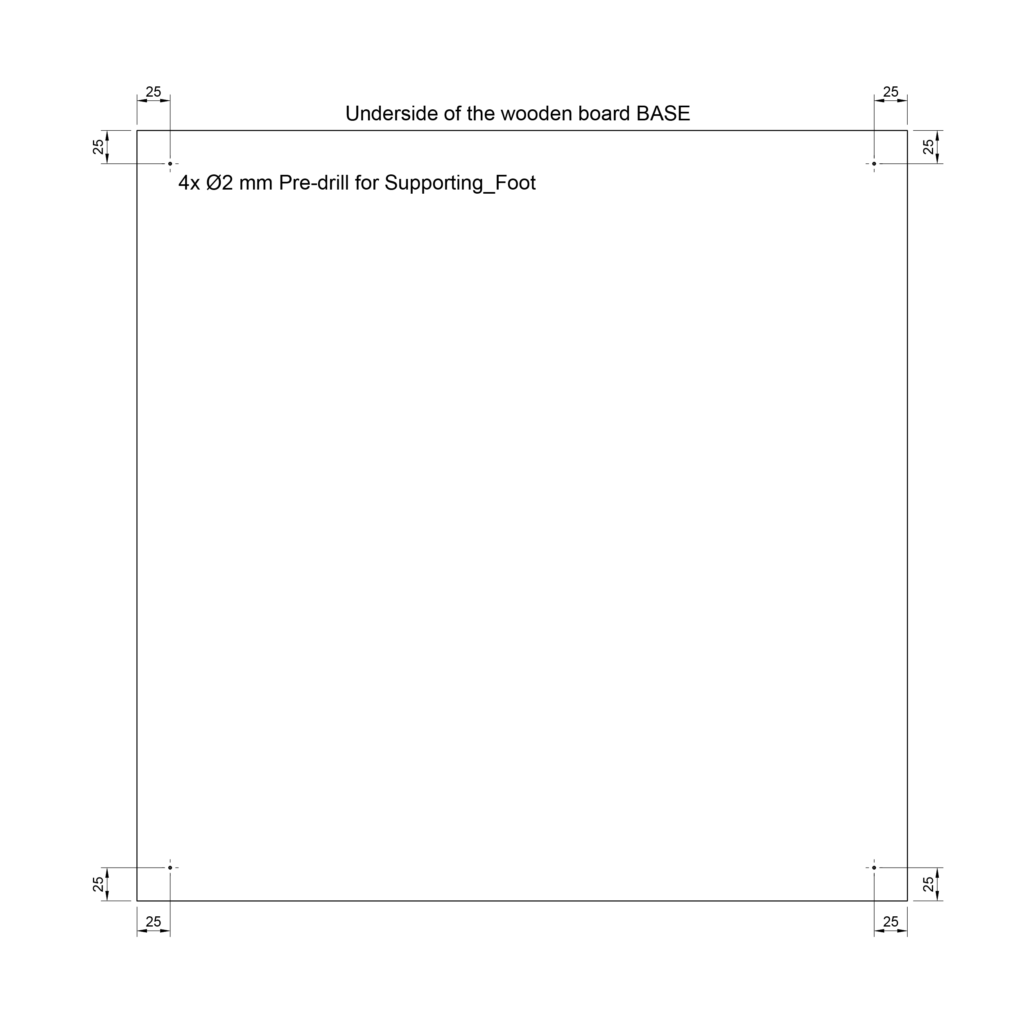
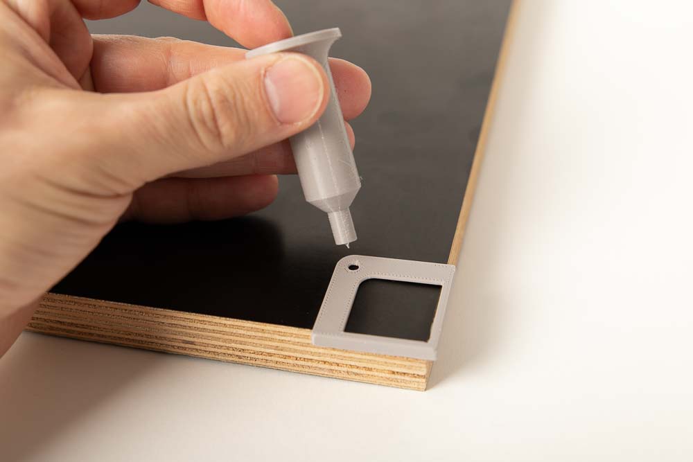
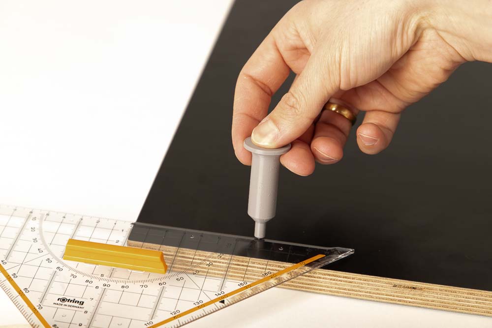
Pre-drilling for the supporting feet: Turn the panel over to the side without tape and label (later the outside). Use the stencil marked STAND (005100_Stencil_Stand) and mark the pilot holes with the marker.
Check all marks with a ruler based on the technical drawings.
Then pre-drill at all the marks, 8x on the later inside face (tape with label) and 4x on the underside of the panel (no tape).
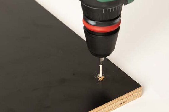
Pre-drill approx. 10 mm deep at all marks with a 2 mm wood drill bit (suitable for the thickness of 18 mm and the 20×4 mm wood screws).
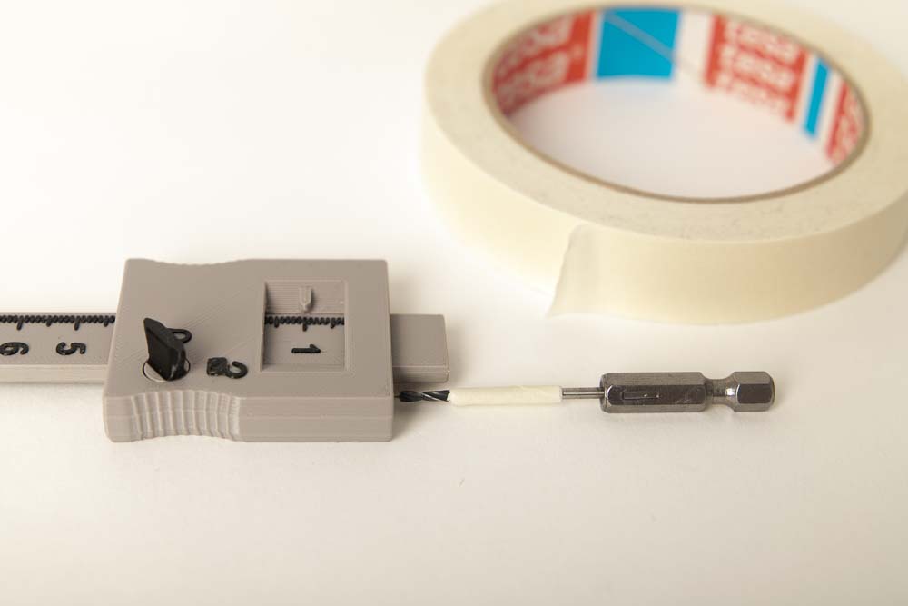
Tip: Mask off the drill bit at the depth you do not want to drill, for example set 10 mm with the depth gauge and mask off the rest of the shaft with tape.
Top panel – mark and pre-drill for the brackets
The Top panel covers the top of the Rear, Left and Right Panels. For this reason, the brackets must also be offset inwards by the panel thickness.
The Top panel is prepared in the same way as the Base panel, again using the two depth gauges and the Bracket_3-sided at the back and the Bracket_2-sided at the front of this panel.
Rear pilot holes: Set the Bracket_3-sided here by the thickness of the wooden panels from the edges inwards. The Left, Right and Rear panels will sit there later.
Simply set and fix the panel thickness on the depth caliper. Then position the bracket on the plate and mark through the holes with the marker.
Front pilot holes: Place the Bracket_2-sided here by the thickness of the wooden panels from the side edge inwards. The Right (or Left on the other side) panel will then sit there later.
Then set and fix 35 mm from the front on one of the depth calipers. Then position the bracket on the plate and mark through the holes with the marker.
Then, as with the Base panel, first check all markings with a ruler based on the technical drawing and then drill approx. 10 mm deep at all markings with the 2 mm wood drill bit, a total of 8 times.
Right panel – mark and pre-drill for the brackets and hinges
This panel is fixed on the right side of the 3D printer enclosure when viewed from the front. The board is later installed between the Top and Base panel. The brackets will later simply be flush with the edges. At the back, however, the Rear panel is going to be framed by the Left and the Right panels, so it is necessary to take the panel thickness into account when positioning the brackets at the back.
At a 3D printer box, whose door opens to the right side, the hinges for the door are attached to this panel on the outside. If you want the door to open on the other side, simply drill the pilot holes shown here on the Left panel.
Rear pilot holes: Place the Bracket_3-sided by the thickness of the wooden panels from the rear edge inwards. Position the bracket flush against the edge at the top edge. Or flush with the bottom edge for the lower bracket.
Then mark the holes through the bracket with the marker.
Front pilot holes: Place the Bracket_2-sided flush with the top/bottom edge here. The bracket is then positioned 35 mm away (depth caliper) from the future opening at the front edge. Then use the marker to mark the wooden panel through the bracket holes.
On the outside of the Right panel (no adhesive tape with label) you going to need four pilot holes marks for the hinges.
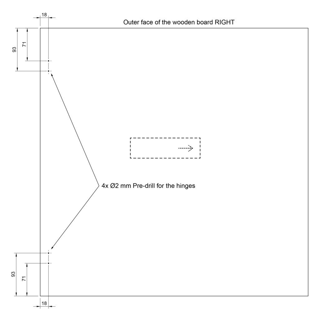
Pilot holes on the outside: Measure here with a ruler 18 mm from the front, and 71 and 93 mm from the top edge of the panel. Place there a mark with the printed marker.
Repeat at the bottom of the board.
Then, as with the other panels, first check all marks with a ruler based on the technical drawings and then pre-drill approx. 10 mm deep at all marks with the 2 mm wood drill bit, a total of 8x on the inside and 4x on the later outside.
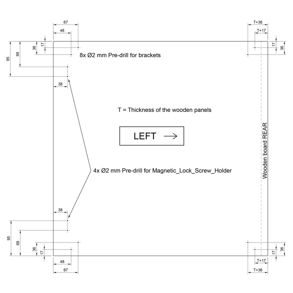
Left panel – mark and pilot holes for the brackets and the magnetic lock screw holder
The Left panel is installed on the left side of the 3D printer enclosure when viewed from the front. The panel lies between the top and base panels, so here, as with the Right panel, there is no additional space to be made for the brackets at the top and bottom. Simply place the brackets flush with the edges. At the back, however, the Rear panel is framed by the Left panel, so it is necessary to take the board thickness into account when positioning the brackets.
In the version of the enclosure shown here in the instructions, the screw holders for the magnetic lock are attached to this panel. If you want the door to open on the other side, simply drill the pilot holes shown here on the Right board.
Rear pilot holes: Place the Bracket_3-sided by the thickness of the wooden panels from the rear edge inwards. Position the bracket flush against the edge at the top edge. Or flush with the bottom edge for the lower bracket.
Then mark the holes through the bracket with the marker.
Front pilot holes: Place the Bracket_2-sided flush with the top/bottom edge here. The bracket is then positioned 35 mm away (depth caliper) from the future opening at the front edge. Then use the marker to mark the wooden panel through the bracket holes.
Simply measure and mark the positions for the pilot holes for the screw holders of the magnetic lock with a ruler.
Pilot holes for magnetic lock: Measure and mark here with a ruler 38 mm from the front edge of the board, and 69 and 95 mm from the top edge of the panel.
Repeat at the bottom of the wooden board.
Then, as with the other panels, first check all marks with a ruler using the technical drawing. Then pre-drill approx. 10 mm deep at all marks with the 2 mm wood drill bit, a total of 12 times.
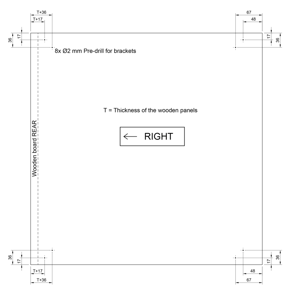
Rear panel – mark and pre-drill for the brackets
The Rear panel is later inserted from behind into the enclosure to fit between all the other panels. It closes the box on the rear side and provide additional stability. The cable for the power supply of the 3D printer and any other cables will later be routed through this panel into the interior of the 3D printer enclosure. For this reason, an opening is sawn in this panel. The 3D printed Cable_Entry_Box is going to be inserted into this opening.
The Rear panel lies between all other panels of the 3D printer enclosure, so here the brackets are all mounted flush to the edges.
Simply place the Bracket_3-sided in the edge and flush on both sides of the panel. Use the marker to pierce the marks through the holes of the bracket into the wooden board.
Then, as before with the other panels, pre-drill all marks with a 2 mm wood drill to a depth of approx. 10 mm, a total of 8 times.
Rear panel – mark and saw the opening for the cable entry box
Using the 3D printed stencil, the centers of the holes to drill and the cutting path can be easily transferred to the wooden panel. The distance of the opening from the edge and if the opening is on the left or right of the 3D printer enclosure can be freely selected. Plan here that the cable routing to the printer in the enclosure is as short as possible.
Important: Leave enough space for the bracket, so choose no less than 50 mm distance to the edge.
Now the 3D printed Stencil_Cable_Entry_Box is used. Simply mark the center points for the radii with the marker.
Then trace the outer edge of the stencil with the marker or a pen that is visible on the wood, so that the later opening is clearly visible.
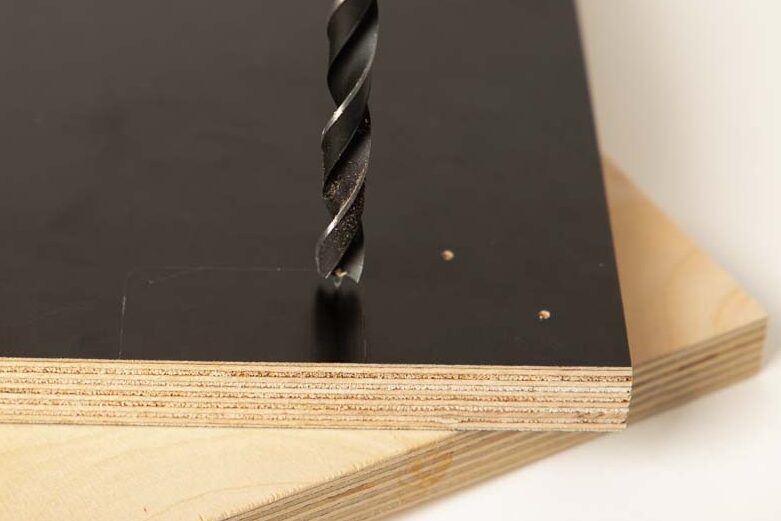
Drill the later radii with a 10 mm wood drill. Start at the hole center marks and drill through.
Tip: Be sure to put a piece of scrap wood underneath, otherwise the edges at the exit opening of the drill may tear out or splinter.
The scrap wood is a wooden panel where it does not matter if you drill into it. Protects the workbench and prevents unsightly tears on the workpieces.
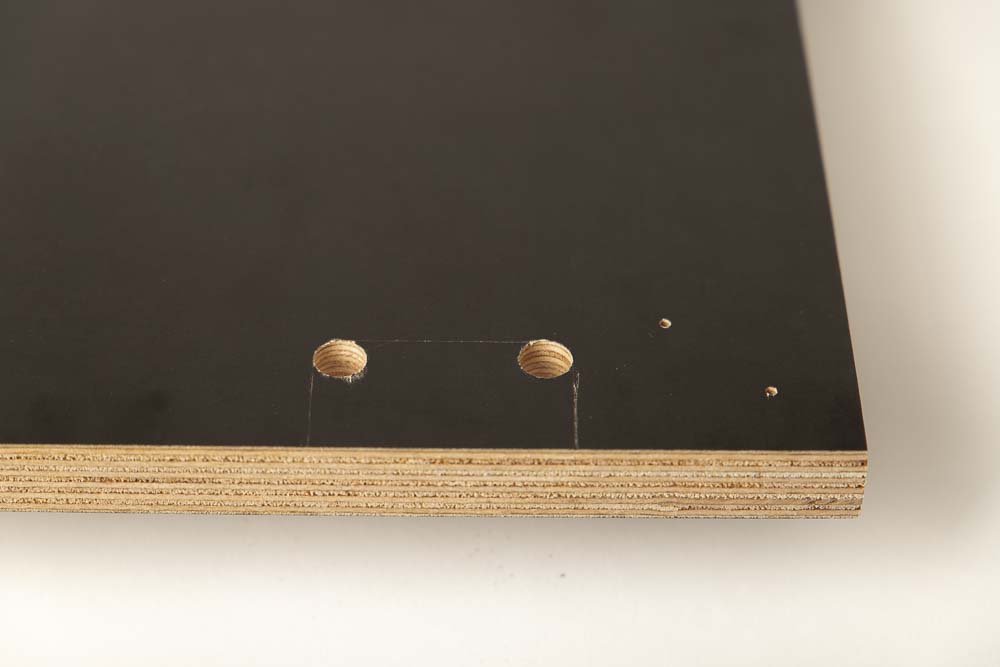
The picture shows the Rear panel with the two 10 mm holes.
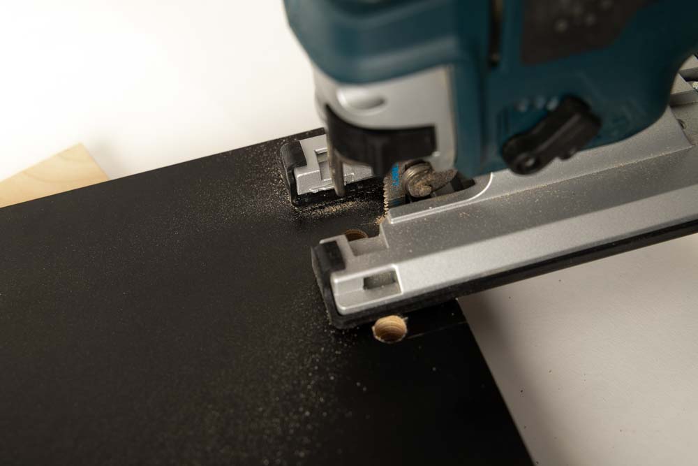
Clamp the panel so that the opening to be sawn is free. Saw out the marked path with a jigsaw or something similar.
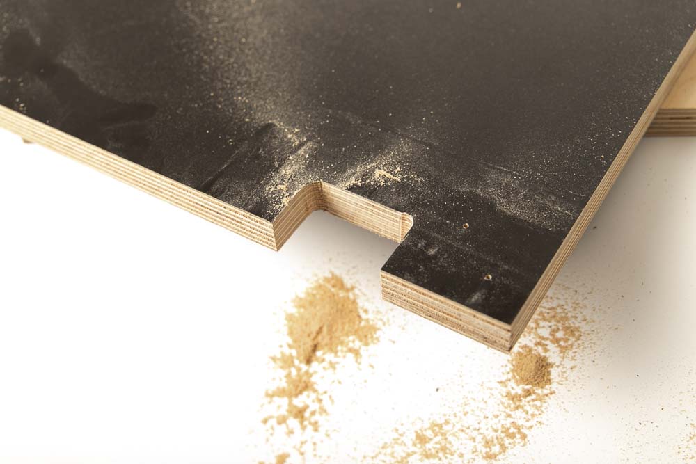
The result should then look like this, I didn’t make the opening very nicely here, but that’s no problem. The cable entry box will later cover the cut-out.
It is best to test right away if the 3D printed part Cable_Entry_Box fits in well. With flexible beams on the side, it should fit easily into the opening and sit well. It is important that it is flush with the lower edge of the panel.
First remove the part again, the cable entry box is inserted into the fully assembled 3D printer enclosure later.
Very good, the preparation of the wooden panels is done, the next step is to prepare the acrylic panel.
Step 3: Machining the acrylic panel
A total of eight holes (diameter 6 mm) for magnetic locks, handle and hinges are drilled into the acrylic (Plexiglass) panel, which will later be installed as the transparent Door. Tips for drilling in acrylic: cast (GS) acrylic panels have less internal stress than extruded (XT) panels, which means that they are less prone to cracking and splinter off during processing. The drill bits used are also important: do not use drill bits for metal, wood drill bits are much better, special plastic drill bits (Plexiglas drill bits) are best. Here in the instructions, standard wood drill bits are used to drill the acrylic (Plexiglas) sheet.
Acrylic Door – pre-drilling for handle, hinges, and magnetic locks
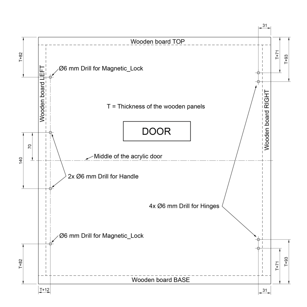
The acrylic panel covers all the wooden panels from the front, on whose front faces the sealing tape will later be glued. In the technical drawing, all panels are marked with dashed lines for orientation.
Depending on the plywood thickness T, it is particularly important to calculate the correct dimensions for the position of the magnetic locks and the hinges. This ensures that these later matches the components mounted on the wooden box.
For example, with a wooden panel thickness of T = 18 mm:
- The dimension T+82 for the magnetic locks then results in 18+82 = 100 mm from the upper or lower edge of the acrylic panel.
- From the left edge, the holes for magnetic locks and the handle are then placed inwards by T+12 = 30 mm.
- For the position of the holes for the hinges, the results are T+71 = 89 mm and T+93 = 111 mm from the top and bottom edge.
- The 31 mm from the right edge always remains the same, regardless of the wooden panel thickness, as the hinges are attached to the outside of the 3D printer case.
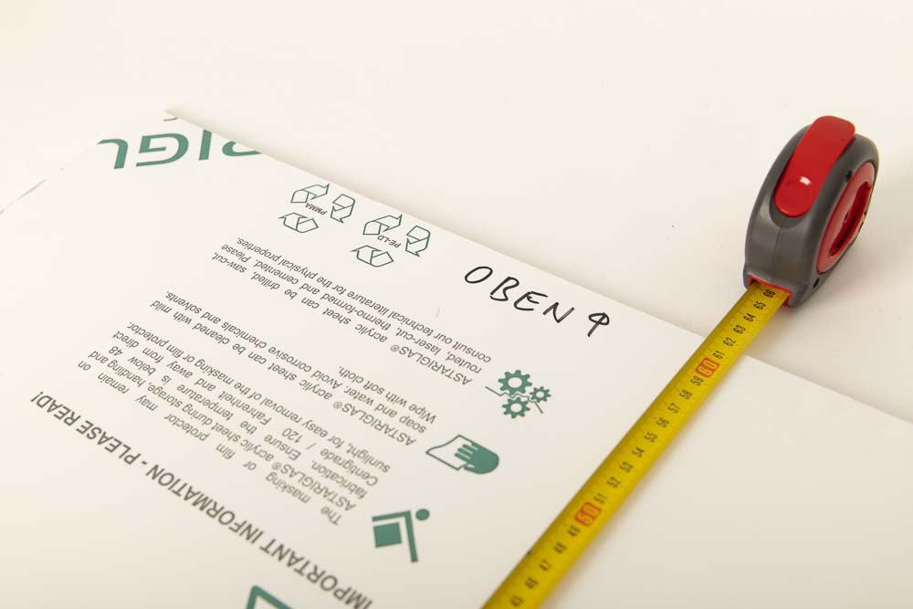
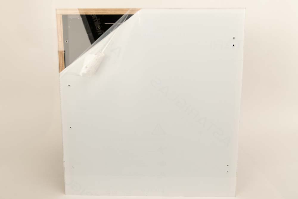
Leave the protective films on the acrylic panel. Check the external dimensions and position the panel correctly. Label where the upper edge will be later with Top. In the picture “Oben” means top in German. The acrylic board used in this guide is 616 x 580 mm (height x width). Top in this case is where the panel measures 616 mm.
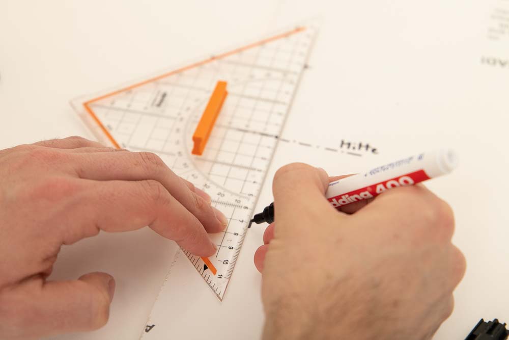
Measure and mark the holes on the left and right side using a ruler. For the handle bores, first mark the center of the door and measure away from there. In the picture “Mitte” means middle in German.

Then drill with the 6 mm wood drill, a total of 8 times. Be sure to put a piece of scrap wood underneath and be careful not to drill too fast or too slow.
After drilling the holes in the acrylic panel, the hardest part of the instructions is done, now all panels are ready for assembling the DIY 3D printer enclosure. Before that, the cable entry box, the hinges, and the magnetic locks are prepared.
Step 4: Preparing the magnetic locks, cable entry, and hinges
In this step, some 3D printing components are going to be pre-assembled so that assembling the whole 3D printer enclosure later is easier.
Required purchased parts
- 6 pcs Socket head cap screws M5x20 mm DIN 912 / ISO 4762 – 12.9 black oxide
- 2 pcs Hex nut M5
- 6 pcs Magnets Neodym 10×2 mm
Required 3D printed parts
- 2 pcs 003200_Hinge_Part_1
- 2 pcs 003300_Hinge_Part_2
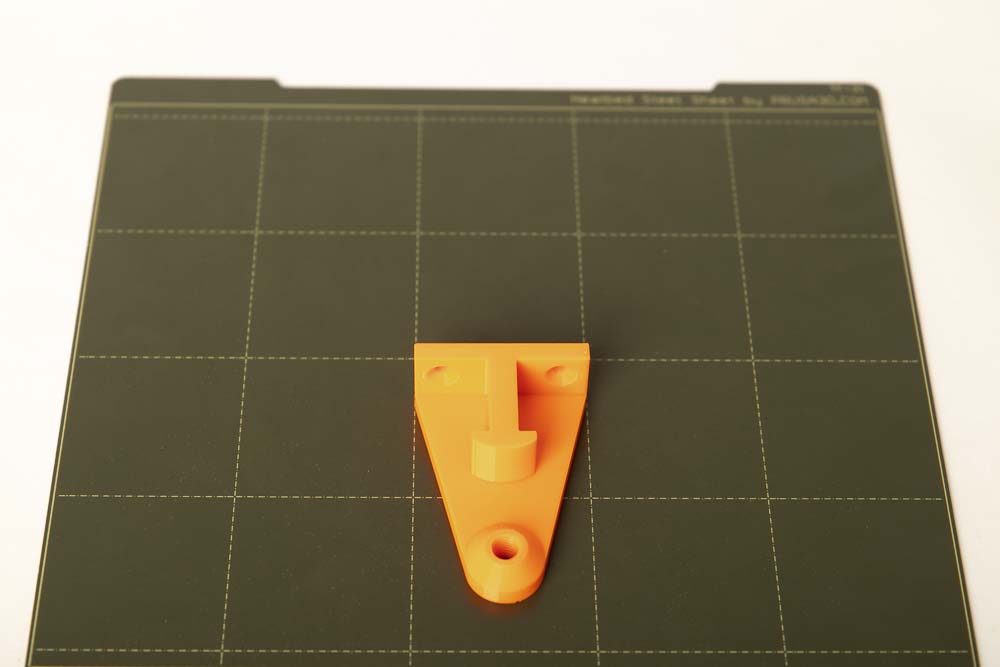
- 2 pcs 003400_Magnetic_Lock_Screw_Holder
- 2 pcs 003500_Magnetic_Lock_Magnet_Holder
- 2 pcs 003600_Magnetic_Lock_Cap
Layer height 0.2 mm and 100% infill (rectangular)
Attention: With the Magnetic_Lock_Magnet_Holder, only two layers of filament (0.4 mm thick) are applied directly to the print bed in the middle of the components. Be careful when detaching. When starting the 3D printing process, make sure the first layer adheres properly.
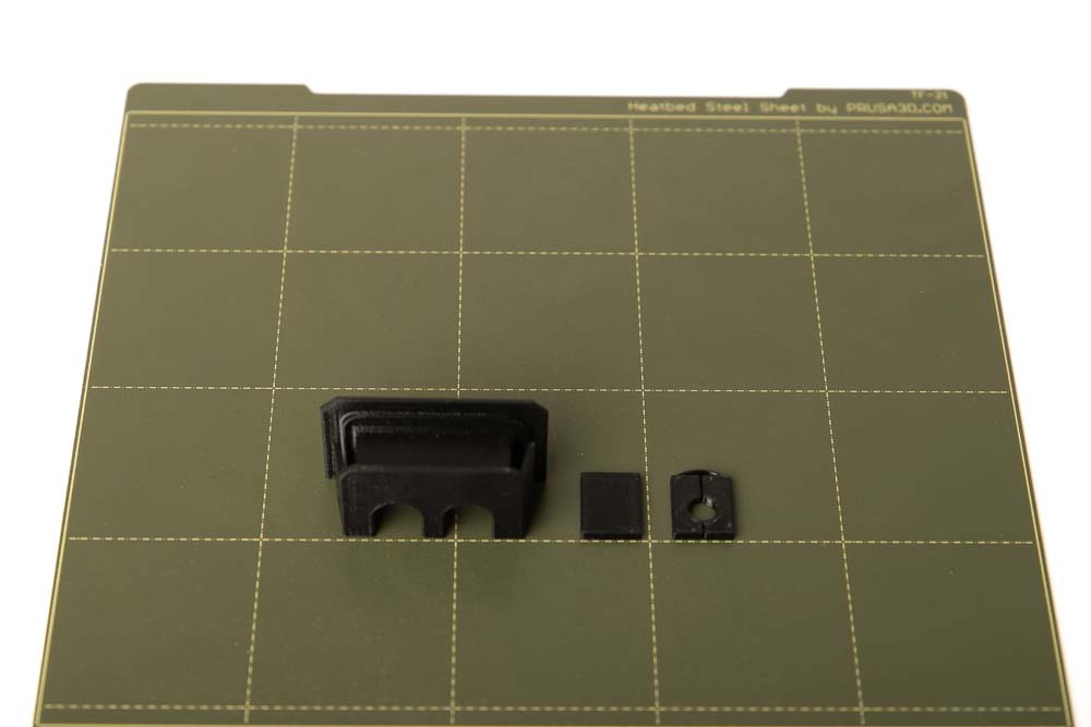
- 1 pc 003800_Cable_Entry_Box
- 2 pcs of inserts – choose the right ones for your cables here
The inserts shown here are:
- 003900_Cable_Entry_Insert_closed
- 004000_Cable_Entry_Insert_Bore_D7
Layer height 0.2 mm and 100% infill (rectangular)
When it comes to 3D printed inserts for cables, it is now important to choose the right inserts depending on the cables to be routed into the enclosure. This is about the power cable for the 3D printer and other cables, such as for LEDs for the interior lighting of the box.
The passage of the filament into the 3D printer enclosure is done using other 3D printed parts, which are explained later in the Step 10: Filament feedthroughs chapter.
Two inserts fit into the two openings in the 3D printed cable entry box, you can choose between three different shapes:
- 003900_Cable_Entry_Insert_closed – this insert simply seals the opening.
- 004000_Cable_Entry_Insert_Bore_D## – for cables with a round cross-section, with 9 different bore dimensions included in the 3D printing templates.
- 004100_Cable_Entry_Insert_Rectangular_W#_L## – for cables with a rectangular cross-section, with 42 different rectangular cut-outs included in the 3D printing templates.
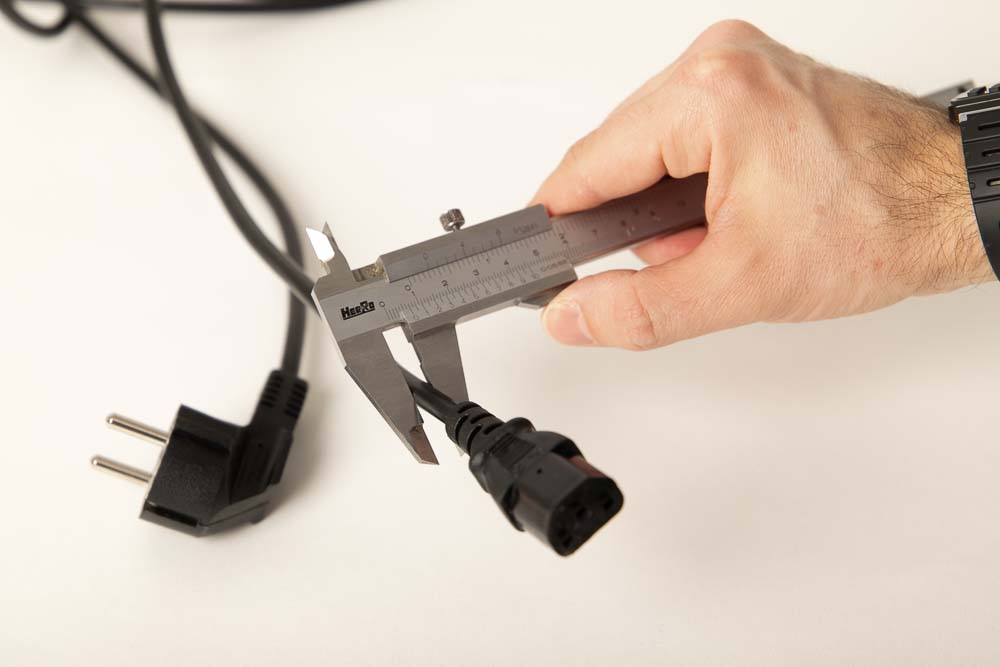
The easiest way is to measure the dimensions of the cable with a caliper and choose the next larger insert.
If you don’t have a caliper, you can use a ruler or the depth gauge to roughly determine the diameter. Then print the next larger insert and check the cable to see if it still has some space and could be moved a little bit. If not, simply print the next larger insert.
The power cable used here has a diameter of 6.8 mm, and the Cable_Entry_Insert_Bore_D7 with a diameter of 7 mm is selected as the appropriate insert.
Assembling the cable entry box
After placing the insert on the cable, check if it is squeezed. If the insert sits too tight on the cable, select the next larger insert, and print it.
Danger of electric shock with a damaged cable! Check if the cable is pinched. If the insert sits too tight on the cable, then do not use the insert, but choose the next larger insert.
If the cable sits in the insert with some play, then press the insert together with the cable into the cable entry box from below, making sure that the cable is not squeezed.
In this guide and shown here, the 3D printer’s power cord is routed through an insert with a bore and a closed insert is used to seal the second opening in the cable entry box.
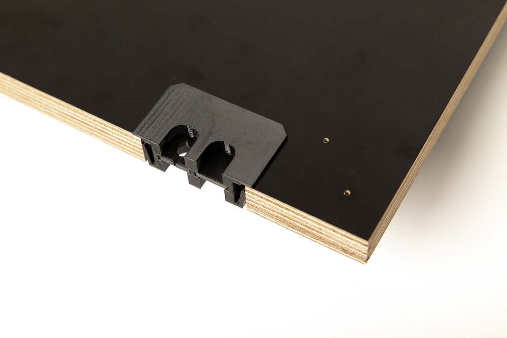
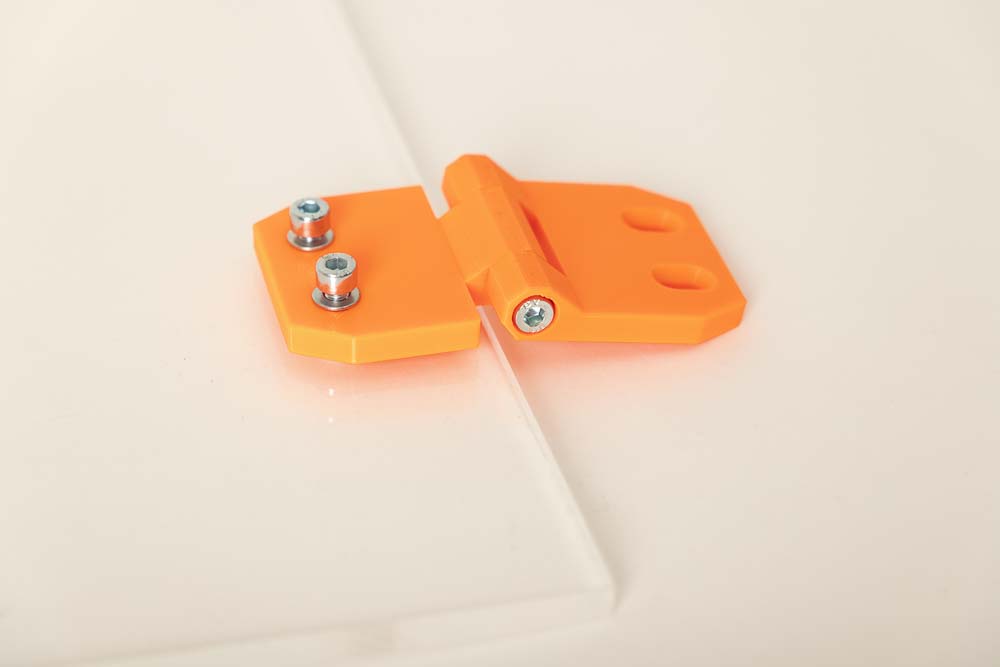
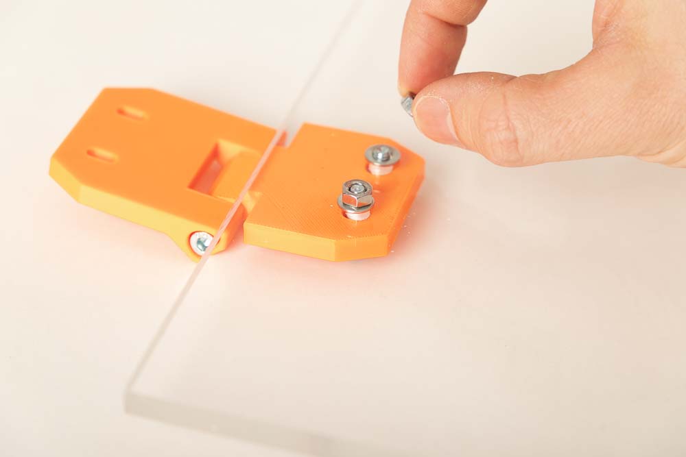
Assembling the hinges
The hinges are easy to assemble. For each of the two hinges, simply put the two 3D printed parts together and fix them with two M5x20 screws each.
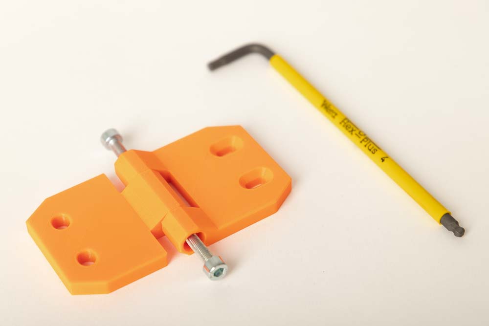
Put Hinge_Part_1 and Hinge_Part_2 together as shown and fix with two M5x20 cylinder head screws.
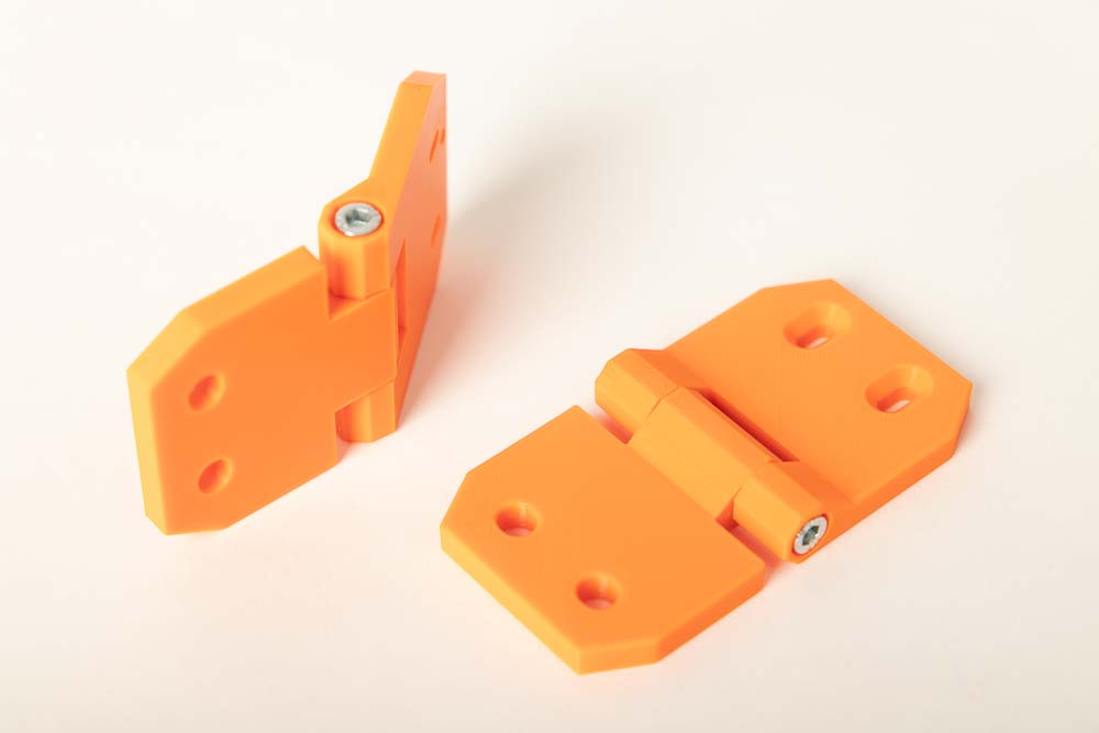
Screw the two screws into Hinge_Part_1 as far as they will go.
Also assemble the second hinge as described.
If the hinges squeak when you move them, unscrew one of the screws again and lubricate the hole with a drop of Bike chain lubricant*.
Assembling the magnetic locks
The assembly of the magnetic locks is a bit trickier, because the magnets are hidden inside, and a M5 nut is pressed-in for the later installation of the locks on the door. First, an M5 nut is inserted into the cap. Then the magnets are sunk into the magnet holder and fixed with the cap.
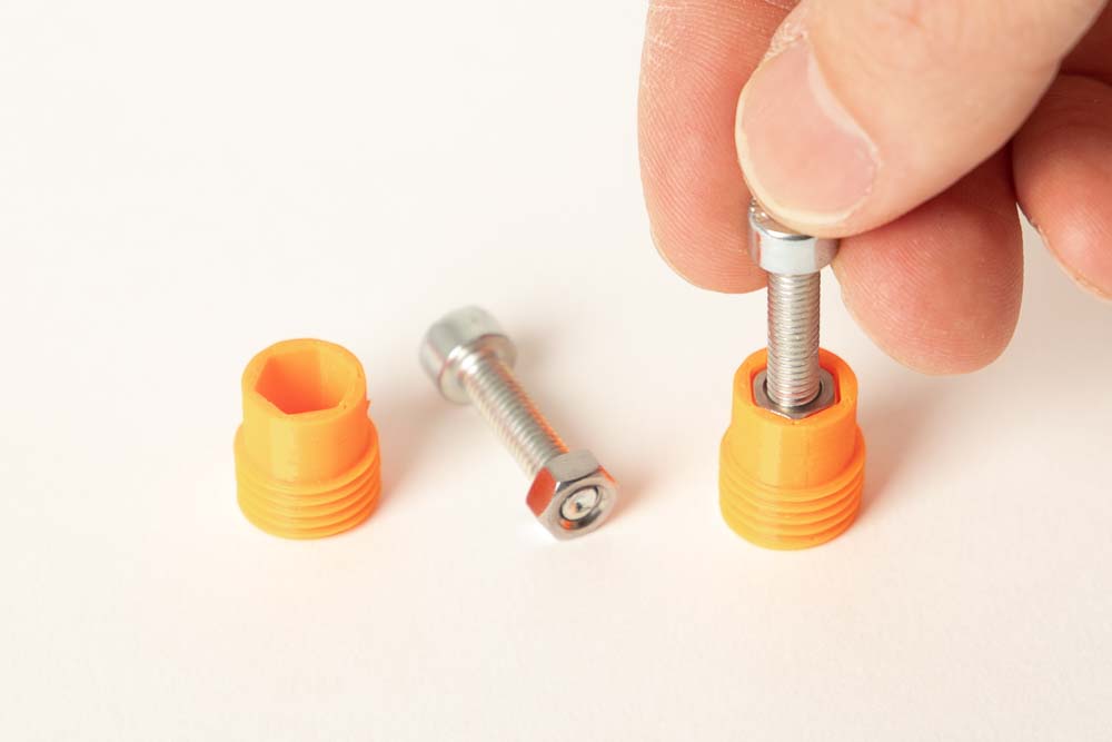
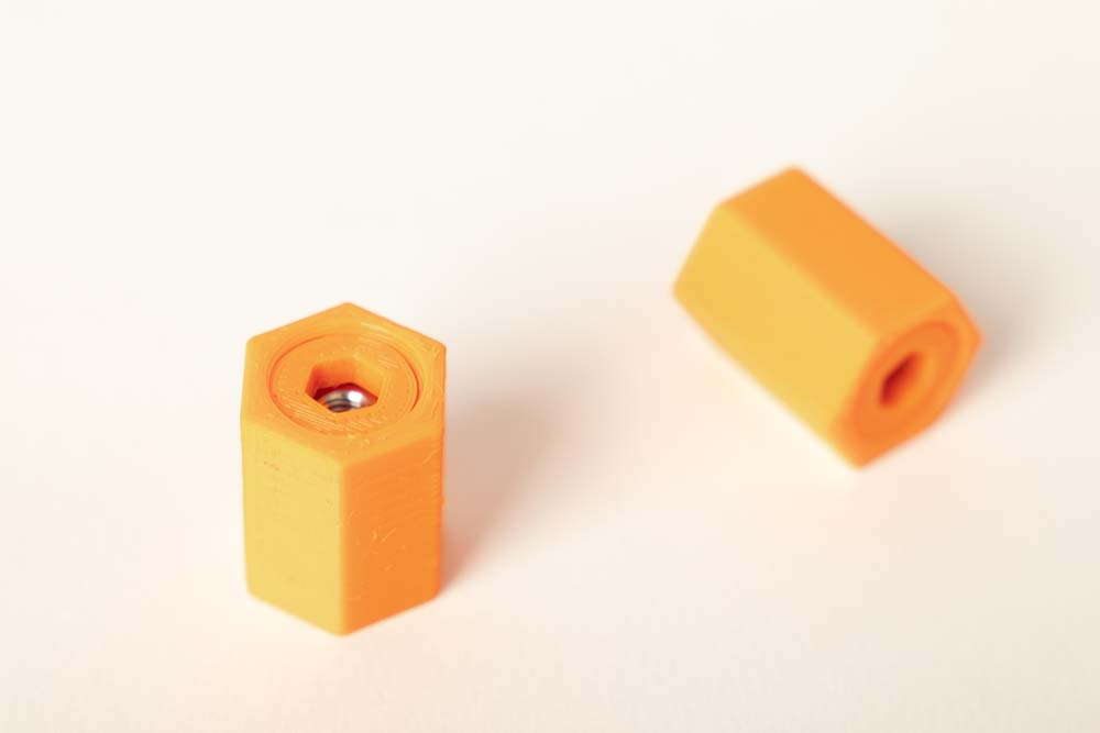
Press the M5 nuts into the Magnetic_Lock_Cap. To do this, screw a M5 nut a few turns onto one of the cylinder head screws. Then press it into the cap. The hexagonal recess gets narrower at the bottom, which wedges and fixes the nut.
Press the nuts in as far as possible without using excessive force. After that, unscrew the screw from the nut and prepare the second cap.
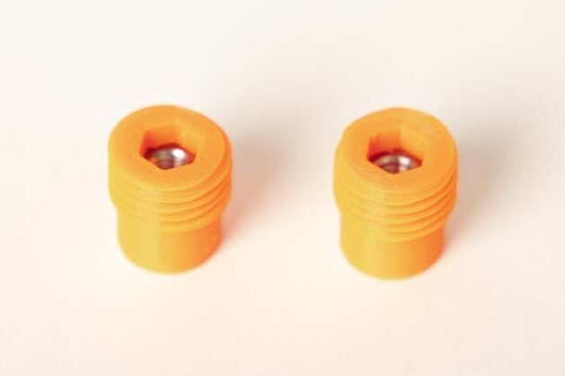
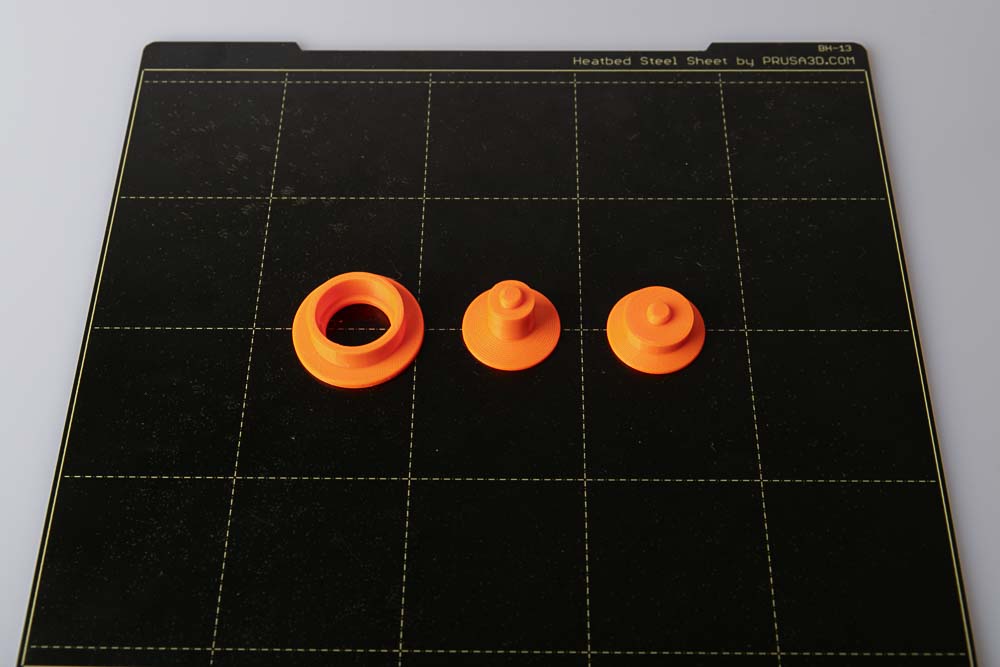
The Magnetic_Lock_Caps with the pressed-in M5 nuts should then look like in the picture.
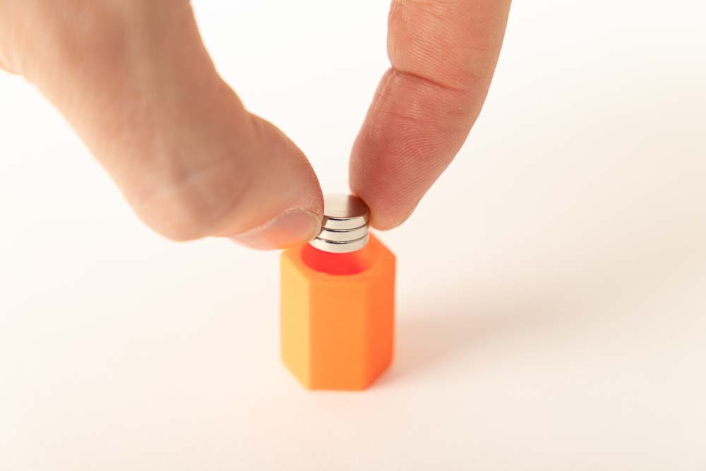
Drop three magnets (stacked on top of each other) into the hole in the Magnetic_Lock_Magnet_Holder.
Align the magnets inside with an M5 screw on the outside.
Screw in the Magnetic_Lock_Cap using a 6 mm Allen key. Do not press the Allen key too deep into the cap to avoid loosening the pressed-in M5 nut.
Tighten the cap on very lightly! There is a risk that the magnets will be pushed out through the thin printed membrane (only 0.4 mm thin) on the underside, and the printed magnet holder could be damaged.
The fully assembled magnetic lock, consisting of cap and magnet holder, ready to be screwed onto the door. Each lock has three magnets and one M5 nut inside.
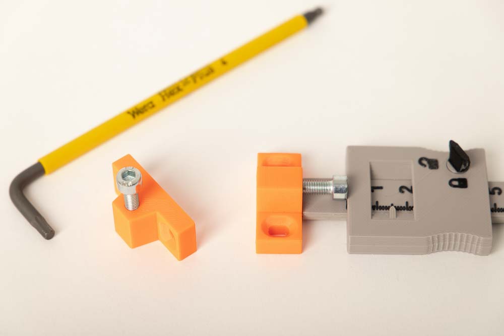
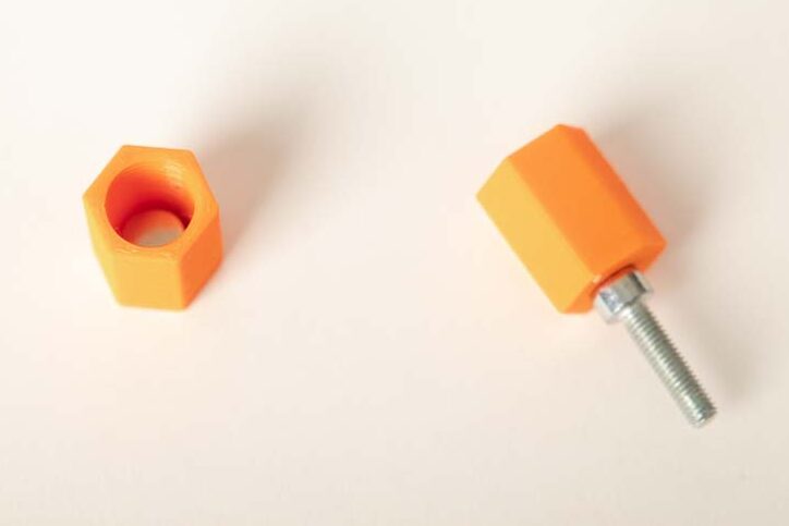
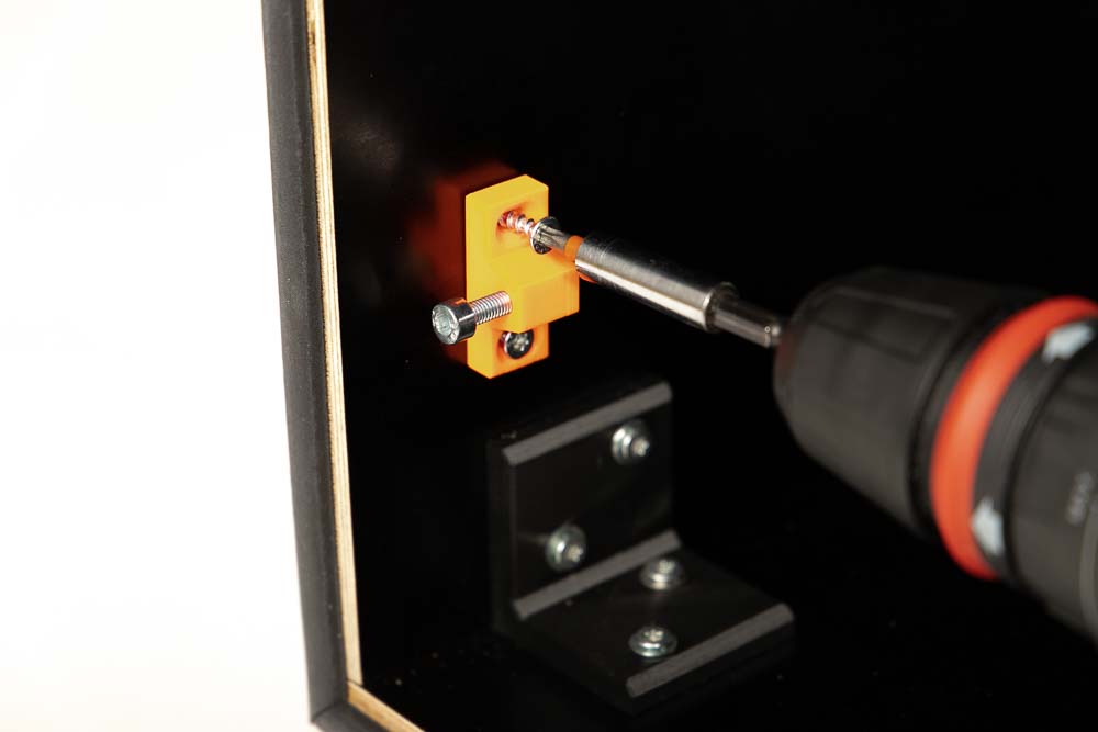
Screw an M5x20 cylinder head screw into the hole in the Magnetic_Lock_Screw_Holder so that about 15 mm of the screw protrudes from the 3D printed part. Here again, the depth caliper included in the 3D print files can be used for setup and measuring.
Step 5: Assembling the 3D printer box
In this step, the wooden case is assembled. This requires the pre-drilled wooden panels, the brackets, the pre-assembled components, and the following parts:
Required purchased parts
- 44 pcs Wood screws #7 x 3/4″ flat head (corresp. 4×20 mm)
- 44 pcs Flat washer DIN125 M5 5.3x10x1 mm (Amazon.com US)*
- Approx. 4 m (13 ft) Sealing tape D-type 9×6 mm – the exact dimension is the circumference of the door
Required 3D printed parts
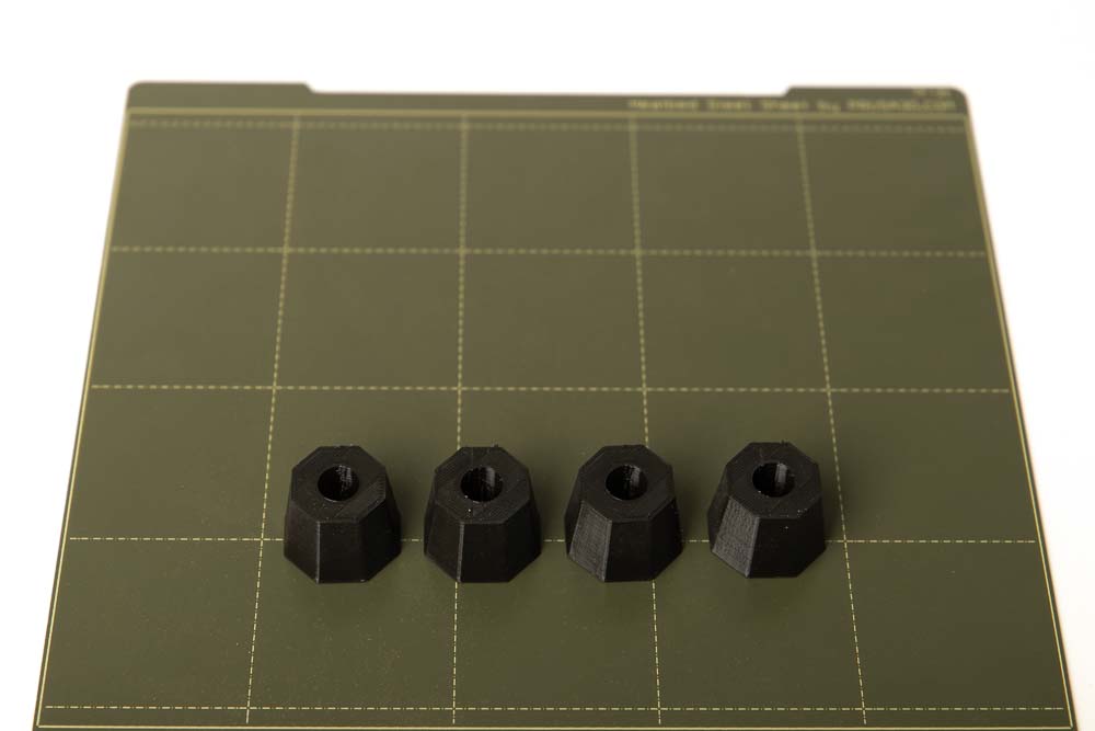
- 4 pcs 003700_Supporting_Foot
These can be printed with PETG with a layer height of 0.2 mm and 100% infill (rectangular).
To achieve better vibration and noise damping, flexible filament was used in these instructions. A Fiberlogy Fiberflex 30D Black* was printed with a layer height of 0.2 mm and 30% infill (rectangular).
Assembling the wooden panels of the DIY 3D printer enclosure
After preparing all the panels, the assembling of the box is easy. Position the printed brackets and secure them with the wood screws and washers. First tighten the screws only to the point that there is still enough play to move the panels a little. Then align the boards to each other, check the flushness and then tighten the wood screws finally.
The position of the wooden panels of the 3D printer enclosure is shown again in the rendering.
Fixing the brackets, always use 4×20 mm wood screws (or choose the best fitting screw depending on your wood panel thickness) and a M5 washer. The holes on the brackets are generously sized so that the brackets can still be moved by 1 – 2 millimeters.
When assembling, only tighten the screws so much that the bracket is almost fixed and can still be moved on the panel. This helps to align the wooden panels to each other and allows for clean, flush alignment.
It is best to start with the Base panel and then build on it. Screw on two Bracket_2-sided at the front and two Bracket_3-sided at the back, so that they can still be moved easily. In the picture the label text “Unten” is German for base.
The screws are only tightened when the panels are exactly aligned with each other.
Attach the Left, Right and Rear panels to it. Screw on again only so tightly that they can still be moved.
Align the panels to each other, paying particular attention to the connection of the Right and Base panels, as well as on the Left and Base panels. Then tighten the screws on the brackets.
If the panels are cut very precisely, the Rear panel should have space of approx. 1 mm between the Right and Left panels. So, depending on how precisely the panels were cut, there could be a small gap between them. But that’s not a bad thing, this is later simply sealed with adhesive tape on the back of the enclosure.
Explanation: The Rear panel was made a little smaller, so that in the event of a dimension of it is too large, within a tolerance range of +/- 1 mm, the Left and Right panels can still be flush with the Top and Base panels.
On the Left, Right and Rear panels, screw two Bracket_3-sided at the front and two Bracket_3-sided at the back in such a way that they can still be moved a little bit.
Put the Top panel on them and fix it with the wood screws, but not tighten them finally. First align the Right and Top panels and then tighten the wood screws. Do this again with the Left and the Top panels.
Do not tighten the screws for the Rear panel yet, this board can be used to compensate for any slanting of the box. In the next step, the box is checked for this.
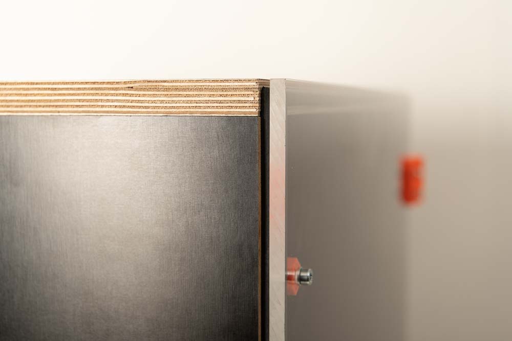
Hold the acrylic plate in front of the box and check if the side walls of the enclosure are square and all edges are flush with the acrylic panel. And hope that the acrylic panel was cut at right angles.
If the acrylic door fits flush onto the wood case as shown in the pictures, then tighten the last loose screws for the Rear panel.
If the panel at the Top is not in line with the Base, this can be compensated for by gently shaping it by hand and then fixing the Rear panel.
Depending on how the panels are cut, there may be a small gap between the Rear panel and the other panels on the back of the enclosure. But that is not a problem, this is sealed with adhesive tape.
Use adhesive tape to seal any gaps that may have formed around the Rear panel.
Alternatively, some silicone or something similar could be applied to the edge of the rear plate so that it is not visible from the outside.
If the 3D printer enclosure is later standing with the back against a wall anyway, some adhesive tape is the easiest.
Installation of the sealing tape on the front of the enclosure
After the wooden enclosure is fully assembled, the seal for the later acrylic door is still missing. This requires the sealing tape and a box cutter. If the corners should also close tightly, they can be glued together with super glue.
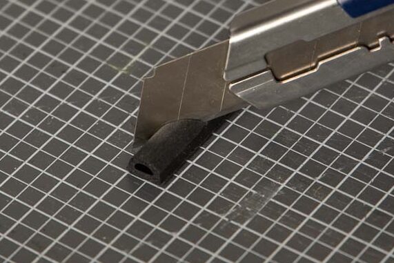
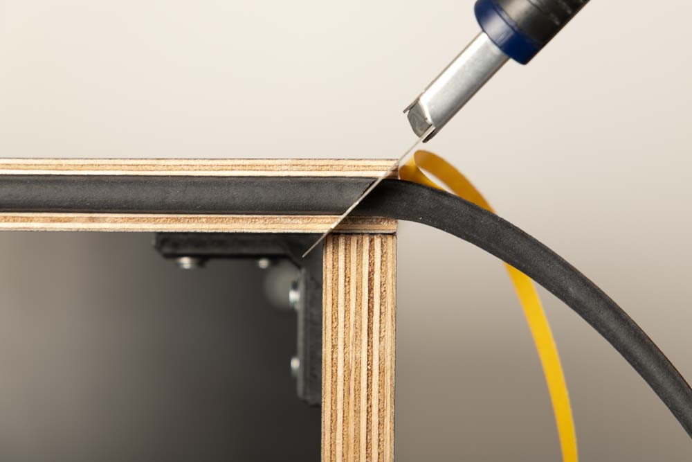
Cut the sealing tape on one side with a box cutter at a 45° angle.
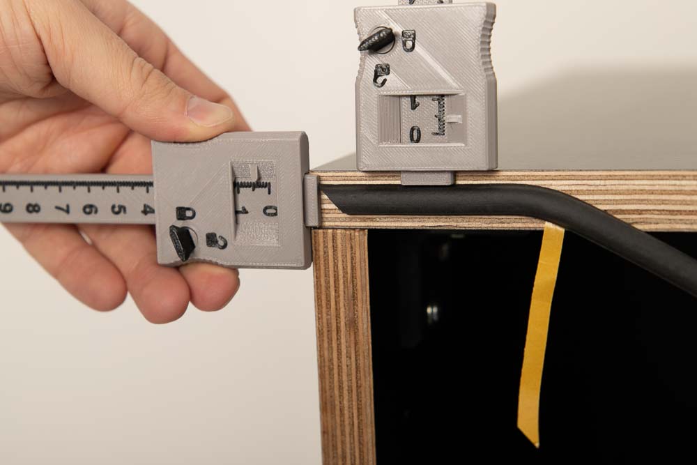
Expose the adhesive strip of the sealing tape a few centimeters and stick it on the left top corner of the 3D printer enclosure. Align the sealing tape in the middle and position the tip of the sealing tape as far from the edge of the Left board as the distance from the sealing tape is to the top edge of the Top panel.
For example, for the enclosure build in this instructions (wood thickness 18 mm and 9 mm sealing tape) this means to position the sealing tape 4.5 mm from the edge of the Top panel, as well as from the tip to the edge of the Left panel.
The depth gauges help here again, the 3D printed tool which models are included in the 3D print files of the DIY 3D printer enclosure.
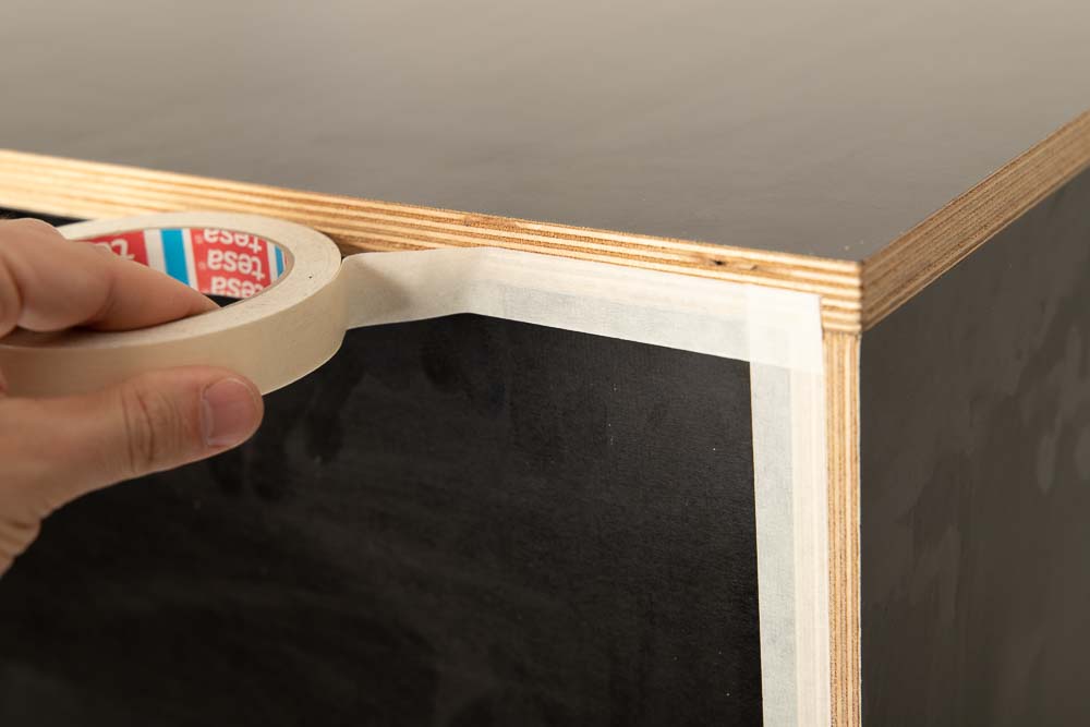
Now expose more and more adhesive strips of the sealing tape and glue the sealing tape parallel to the edge of the board up to the right side of the enclosure.
Then use the box cutter to shorten the tape at a 45° angle directly on the enclosure. To get the angle exactly, put the cutting line through the inner and outer corner of the enclosure. As a result, the tip of the sealing tape is just as far away from the right edge of the panel as the edge of the sealing tape.
Remove the excess sealing tape from the box.
Now cut the remaining sealing tape diagonally on a work mat at a 45° angle.
Then uncover some adhesive again and attach it to the first sealing tape and connect as cleanly as possible.
Glue downwards parallel to the edge of the enclosure and over the bottom of the case as before.
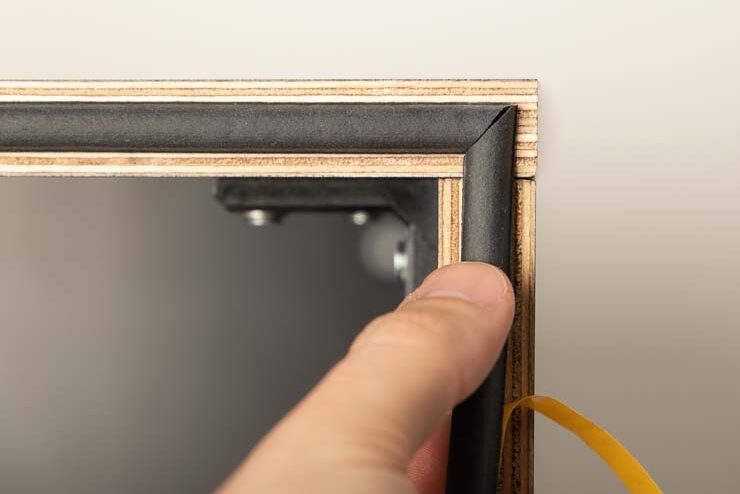
Now repeat these steps until the fourth strip of sealing tape connects to the first. Make the last cut here so that the corner is neatly closed.
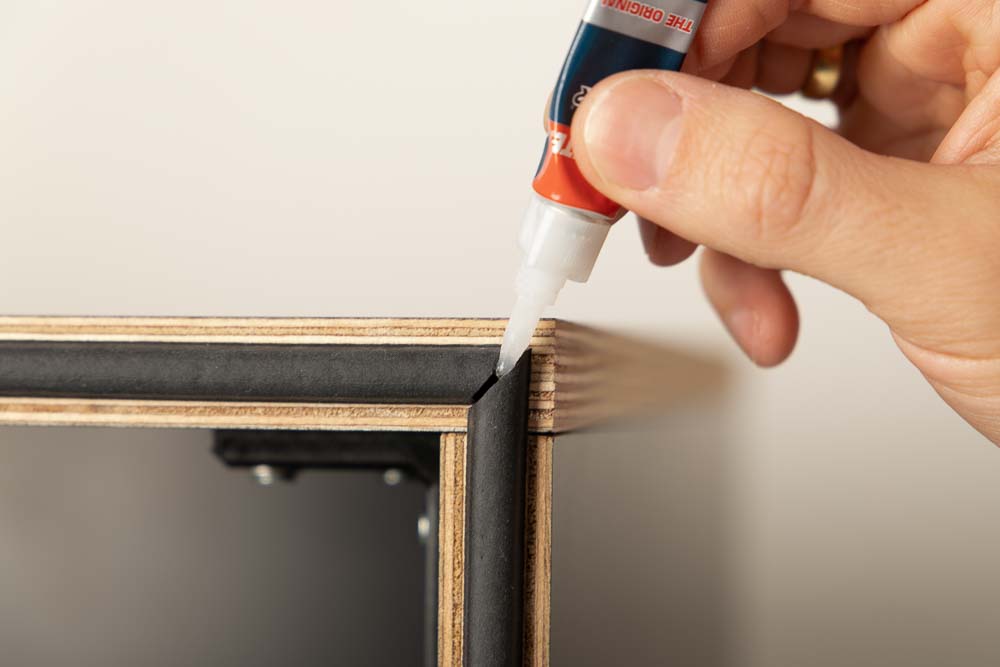
If you want the sealing tape look even cleaner, the individual sealing tape strips can be glued together at the corners with super glue.
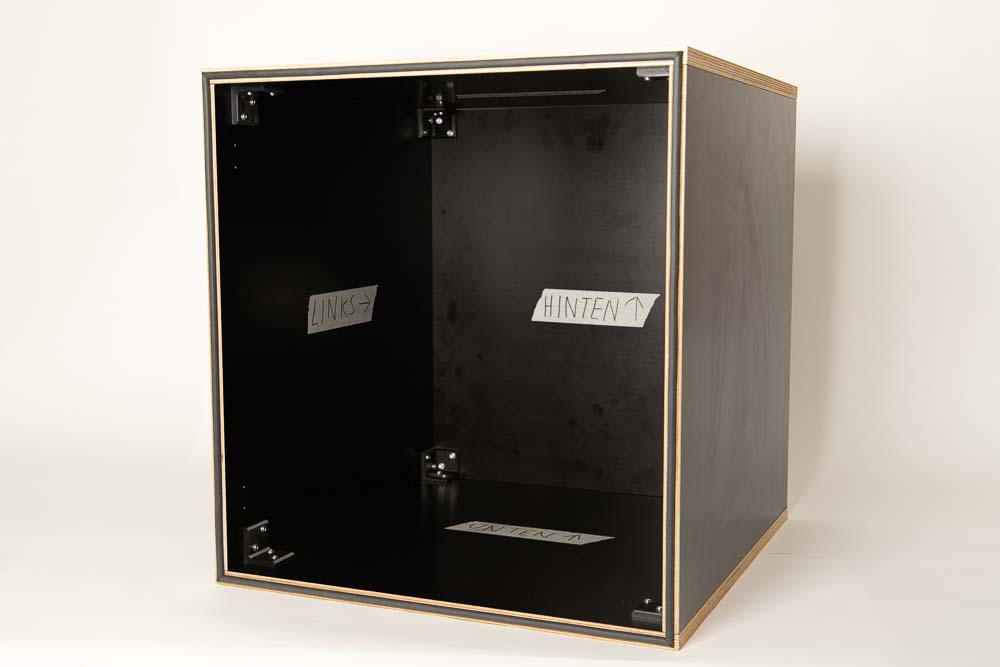
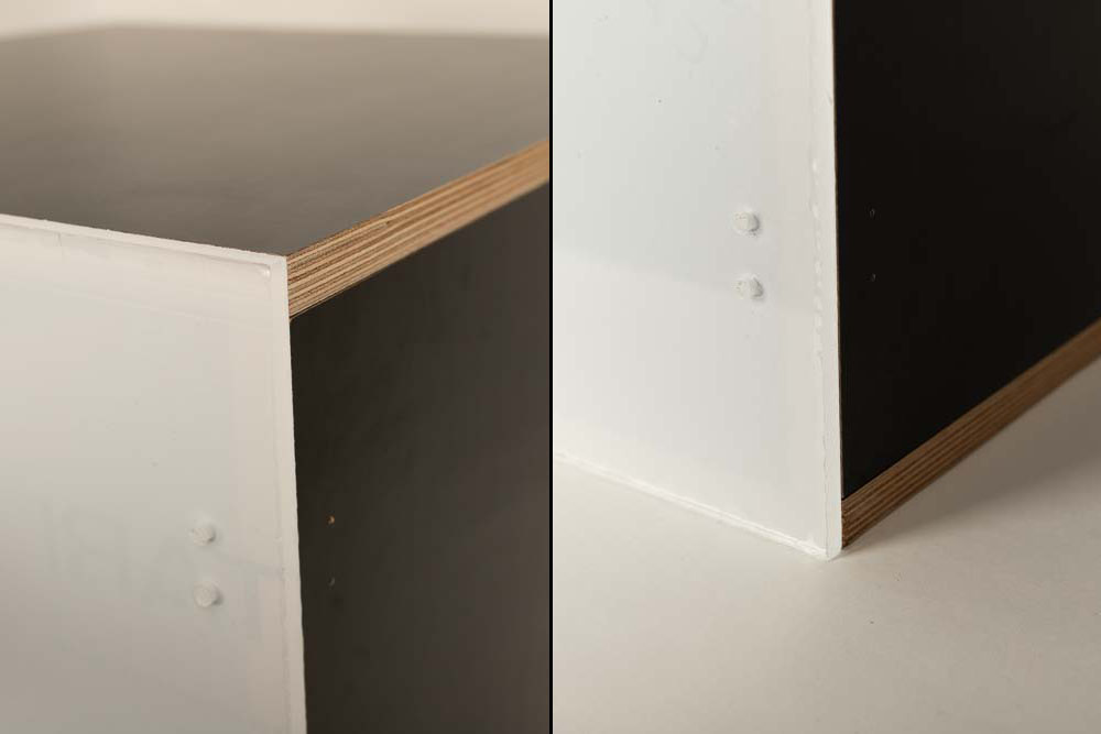
Once the sealing tape is attached, the 3D printer enclosure is now ready for the supporting feet and the door. In the picture the German labels “Links” for left, “Unten” for base, and “Hinten” for rear are used. Maybe this is useful for the next Oktoberfest.
Installation of the supporting feet on the 3D printer box
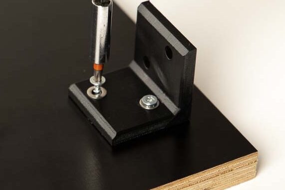
The feet are screwed into the pilot holes in the Base plate. To do this, tilt the enclosure backwards so that the underside is easy to reach and have the feet, screws, and washers ready.
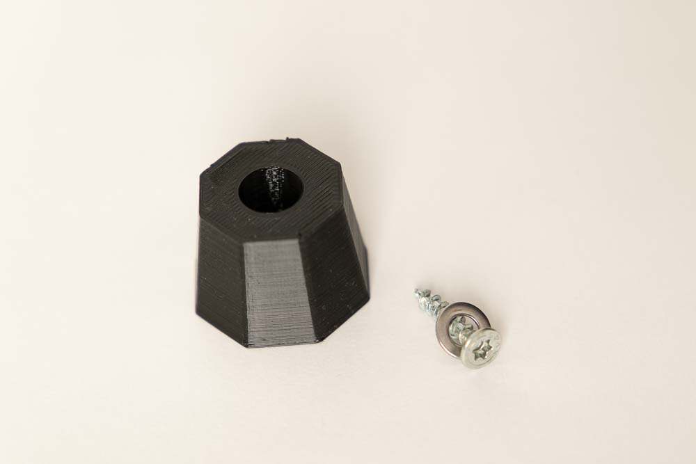
The feet are each mounted with a wooden screw and a washer. To do this, thread the washer onto the wood screw.
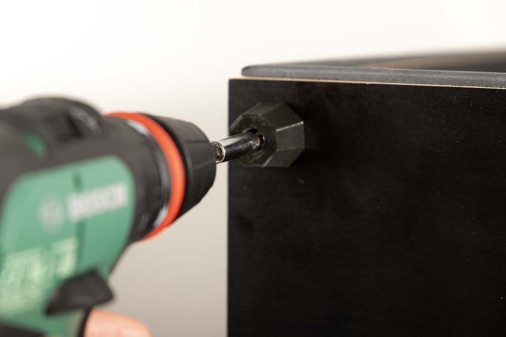
Insert the screw including the washer into the hole provided in the supporting foot and screw it into the pre-drilled holes on the Base panel.
Repeat this until all four supporting feet are fixed on the Base.
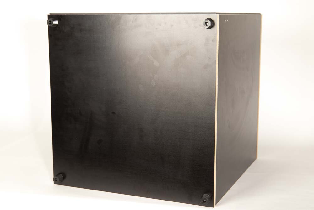
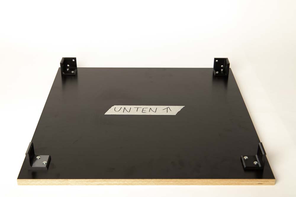
3D printer box from below with the mounted feet.
Step 6: Assembling the acrylic door
Now the last 3D printed parts are installed on the door. The remaining cylinder head screws, washers and nuts are required for this. When attaching with the screws, it is important that the washers are used, so the acrylic is not stressed too much, which prevents cracks.
Before attaching the 3D printed parts, remove all protective films from the acrylic plate.
Required purchased parts
- 8 pcs Socket head cap screws M5x20 mm DIN 912 / ISO 4762 – 12.9 black oxide
- 4 pcs Hex nut M5
- 12 pcs Flat washer DIN125 M5 5.3x10x1 mm
Required 3D printed parts
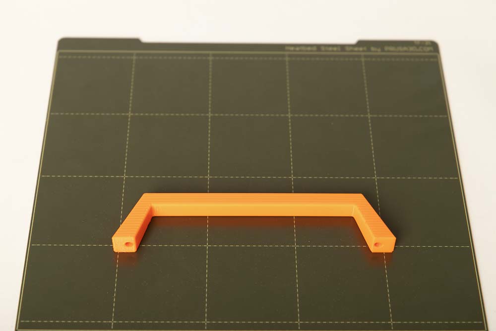
- 1 pc 003100_Handle
Layer height 0.2 mm and 100% infill (rectangular)
Installation of the handle
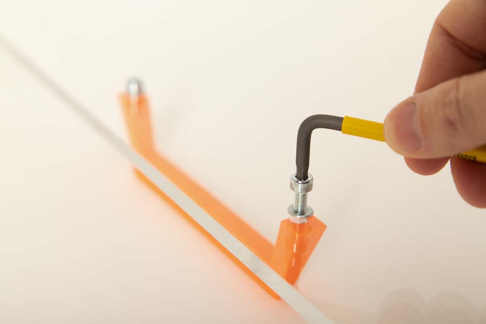
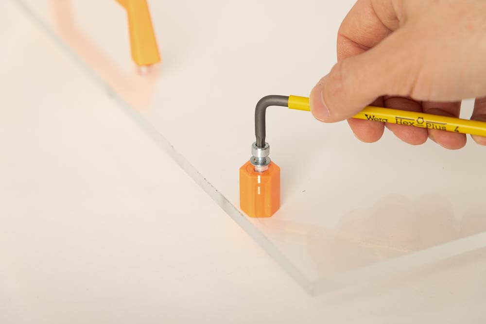
The handle has two holes that are slightly smaller than the threads of the M5 screws.
To install the handle, simply thread a washer onto a cylinder head screw, insert through one of the center holes in the door. Then insert the screw into the hole in the handle, and screw tight.
Do not tighten the screws excessively, this could damage the 3D printed part or the acrylic sheet.
Installation of the magnetic locks
The pre-assembled magnet holders are required here. These are attached to the door with cylinder head screws and washers.
Thread a washer onto a cylinder head screw as before. Then thread the screw from the later outside through one of the outer bores of the acrylic panel.
On the inner side of the door, fix one of the assembled magnet holders by using the internal M5 nut.
Do not tighten the screws excessively, this could damage the 3D printed part or the acrylic door.
Repeat the assembly for the second magnet holder.
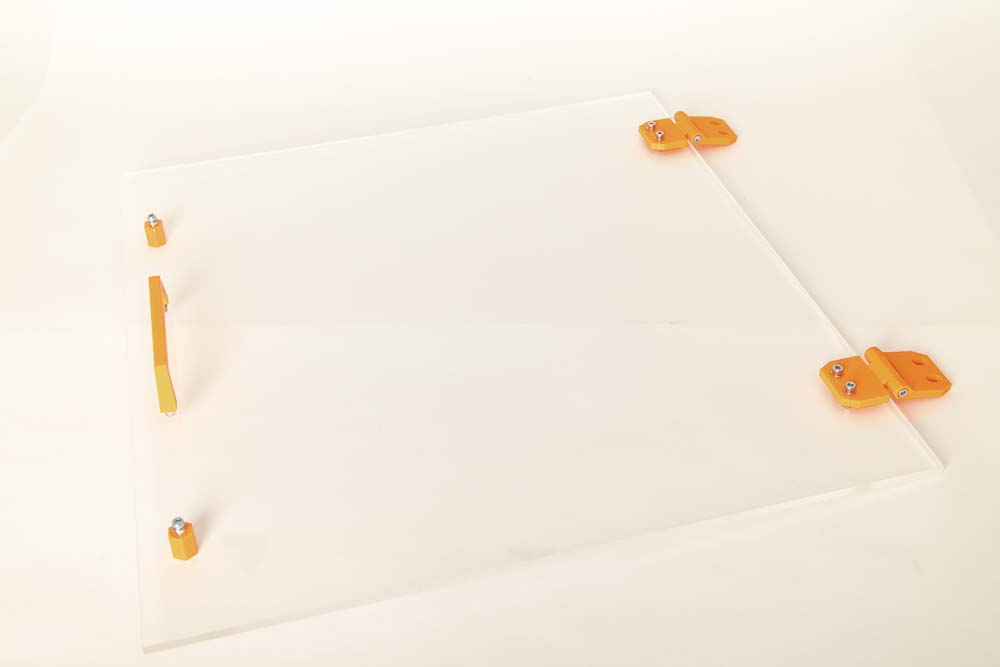
Installing the hinges on the door
The hinges have simple bores for the cylinder head screws on one side (Hinge_Part_1) and slotted holes with chamfers for the wood screws on the other side (Hinge_Part_2).
Thread one washer onto each cylinder head screw. Then insert the two prepared screws through the through-holes from what will later be the outside of the hinge.
Then insert the hinge including the screws through the two upper or lower holes, from the later outside of the door.
Then put two washers on the screws on the later inside and secure with two M5 nuts.
Tighten the M5 nuts only by hand.
Do not fully tighten the nuts. After this step, the hinge should still be easy to move on the acrylic panel. The final tightening of the nuts follows later, when adjusting the door.
Repeat the assembly steps for the second hinge.
Now the door is ready for installation on the 3D printer enclosure.
Step 7: Install and adjusting the door
First, in this step, the screw holders for the magnetic lock are mounted in the DIY 3D printer box. Thereafter, the door is fixed to the enclosure and adjusted.
Required purchased parts
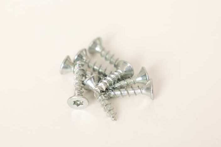
- 8 pcs Wood screws #7 x 3/4″ flat head (corresp. 4×20 mm)
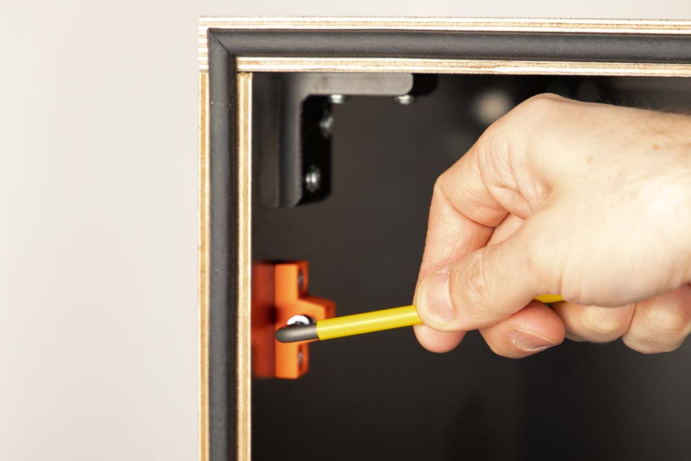
Installation of the magnetic lock screw holders in the 3D printer box
Fix the two prepared screw holders into the 3D printer enclosure with the wood screws. Use the pre-drilled pilot holes on the Left panel.
When doing so, tighten the screws as centrally as possible in the slot holes, and ensure that the 3D printed part is aligned parallel to the edge of the panel.
Attaching the door to the DIY 3D printer enclosure
The hinges are attached to the wooden panel with wood screws.
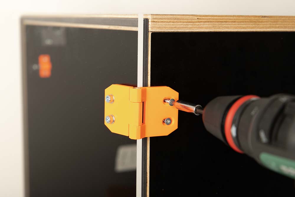
To do this, screw four wood screws through the hinges into the pre-drilled pilot holes provided for this purpose on the Right panel.
Do not tighten the screws completely yet so that the hinges can still be moved along the slotted holes.
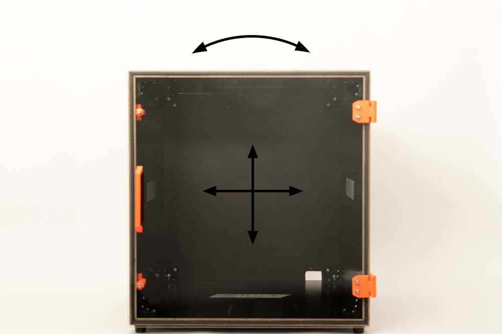
Setting up the door on the self-made 3D printer box
The last step is to adjust the door. The first adjustment is about the pressure of the door against the sealing tape. The second is the position of the door in relation to the built enclosure.
- The pressure of the door on the sealing strip is regulated by means of the cylinder head screws in the magnetic lock screw holders and via the slotted holes in the hinges.
- The position of the door in relation to the wooden 3D printer cabinet is adjusted using the cylinder head screws and nuts on the hinges on the acrylic panel.
The pressure on the sealing tape and the adhesive strength of the magnetic closure are adjusted via the elongated holes in the hinges and the cylinder head screws in the screw holders.
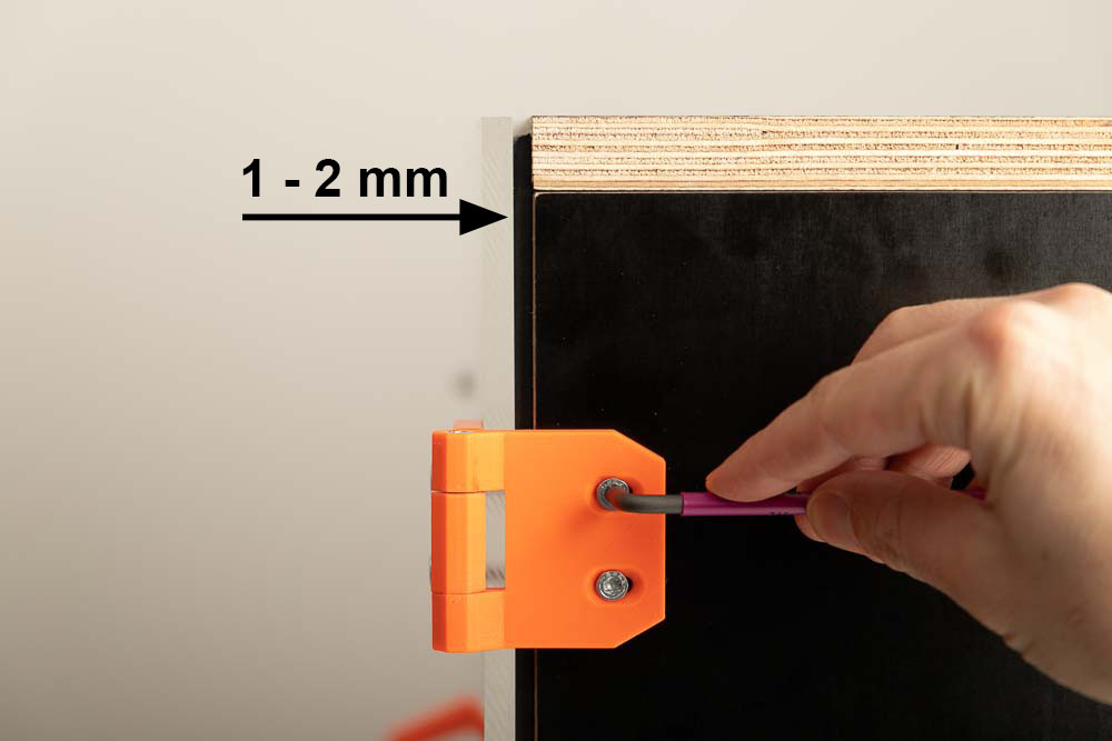
First press the closed door on the hinges in the direction of the wooden enclosure so that the sealing tape is visibly squeezed by 1-2 mm. In this position fix the hinges to the box with the wood screws.
Do this for the hinges at the top and bottom, making sure the top and bottom of the door are the same distance from the edge of the wooden box.
After that, the magnetic locks are about to be adjusted. To do this, first close the door and check whether the magnet holder is in contact with the opposite cylinder head screw.
It is also possible that there is so much gap between the magnet holder and the screw in the screw holder that the magnetic force is too low to keep the door closed.
The optimal setting is where the cylinder head screws just don’t touch the magnet holder when the door is closed. Then the door seals well on the sealing tape and the magnetic force keeps the door firmly closed.
The distance between magnet holder and screw is adjusted by screw the cylinder head screw in or out of the screw holder.
Do this step by step until the magnet just does not touch the screw, but there is still enough magnetic force to keep the door firmly closed.
If this is the case, the sealing tape is squeezed a bit and the door seals well.
Adjust both magnet locks until the door closes and seals properly. The final positioning of the door is carried out using the cylinder head screws on the hinges.
It is best to work step by step here, with one screw-nut combination per hinge only being tightened so little that it holds the door in position but can still be moved with a little force.
Then set up the closed door until the edges match those of the box. Then tighten the cylinder head bolts and nuts on the hinges.
Do not tighten the screws excessively, this could damage the 3D printed part or the acrylic door.
If a much larger box is planned than the one presented here, the closing and sealing of the door can be improved with even more magnetic locks. For example, three magnetic locks can be attached to the Left panel or two additional locks to the Top and Base panels.
Step 8: Place the 3D printer in the enclosure
The assembly of the 3D printer enclosure is now done except for the filament passage. In this step, your 3D printer is placed and positioned optimally in it. Then the optimal position for the filament feedthrough can be determined.
If your enclosure is planned in such a way that the filament spools are accommodated in it, you are almost done after this step. You only need to do the test run in Step 11: Test run of the self-made 3D printer enclosure.
Feeding through the power cable and position the 3D printer in the enclosure
In the chapter Step 4: Preparing the magnetic locks, cable entry, and hinges, the selection of inserts and assembly of the cable entry box was already shown. The prepared box and the cable or cables are now needed for the installation.
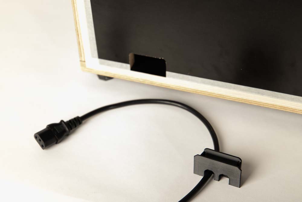
The cable entry box can be pushed into the opening from the inside of the enclosure or from the outside. I prefer the assembly from the outside.
To do this, the device plug of the cable must be on the opposite side of the entry box flange, like shown in the picture.
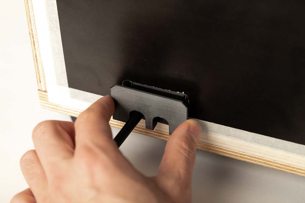
Slide the prepared box into the opening of the 3D printer enclosure.
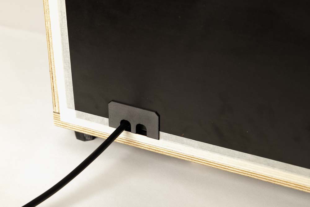
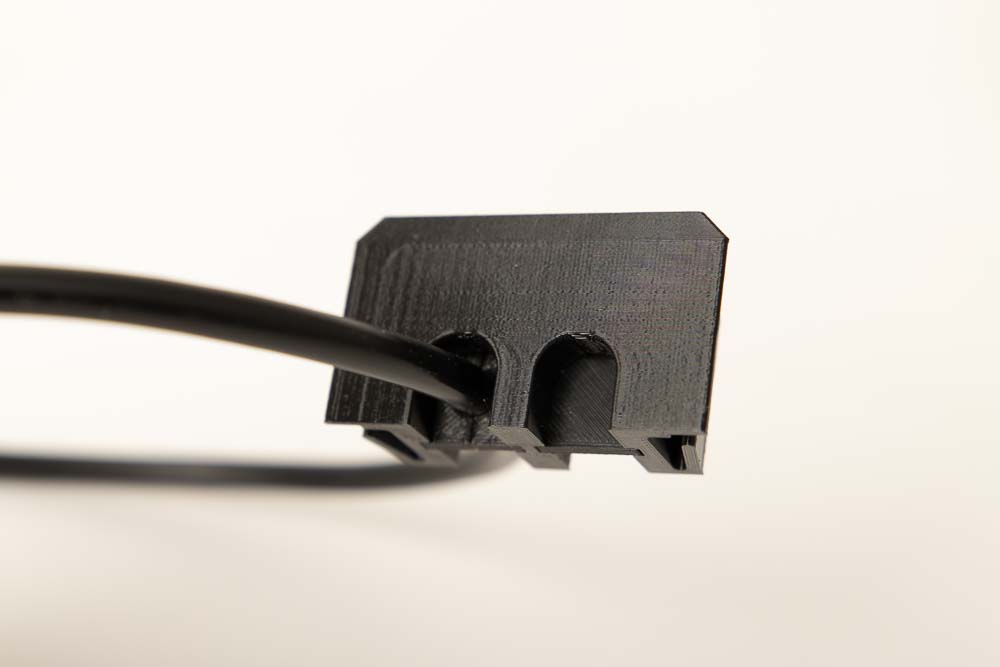
The box sits tightly in the 3D printer enclosure.
Installation is also possible from the inside. To do this, insert the power cable into the cable entry box so that the device plug is on the same side as the flange of the box. Then slide the box into the enclosure opening, but now from the inside.
Then position the 3D printer in the 3D printer enclosure. If you got a damper board, first place it in the enclosure and then position the printer on it.
Check if the 3D printer is standing well and cannot slip. The 3D printer must not slip later during operation!
When placing, make sure that the moving parts of the 3D printer do not touch the enclosure walls when moving. Be sure to carry out a test run and check if moving parts are touching the enclosure or any cables.
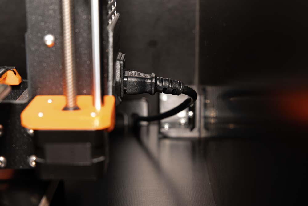
Then connect the power cable and, if necessary, pull any excess cable out of the back of the enclosure to keep the cable routing in the enclosure short and clean.
It is also very important to check if any cables are touching the 3D printer, especially pay attention to the moving parts of the printer. Go through all maximum displacements of the axes in a test run. If a cable touches the 3D printer somewhere, then change the 3D printer position, the cable length, or the location of the cables so that this is not possible anymore.
Risk of electric shock or fire! Be sure to check and make sure that the cables are not in contact with the 3D printer, especially the moving parts. Danger of cable breakage or abrasion of the cable insulation, thereby exposing current-carrying strands.
If the 3D printer is well and securely housed in the 3D printer enclosure, proceed with the next step. If no filament passage is needed in your enclosure, then you can skip Steps 9 and 10 and go straight to the final tests in Step 11: Test run of the self-made 3D printer enclosure.
Step 9: Determine the position for the filament feedthrough
If the filament in your 3D printer setup is later to be fed into the enclosure from the outside, the last step is to install the filament feedthrough. To do this, the position for the passage is first determined and then, in Step 10: Filament feedthroughs, the suitable parts are printed and installed.
Do you already have a 3D printer enclosure and only need the filament feedthroughs and the pulley? By popular demand, the files are now also available to buy individually: 3D print files of the DIY filament feedthroughs with pulley
Determination of the position of the filament passage
This chapter shows a few examples of how to feed the filament into the enclosure, which can then be easily adapted depending on your 3D printer and the planned 3D printer setup.
There are three basic questions:
- Should the filament be delivered in a pluggable PTFE tube?
- From which direction the filament is later fed to the 3D printer enclosure?
- From which direction does your 3D printer pull in the filament?
Possible example setups are explained below, using the Prusa i3 MK3 (Direct Drive Extruder) and Prusa Mini (Bowden Extruder).
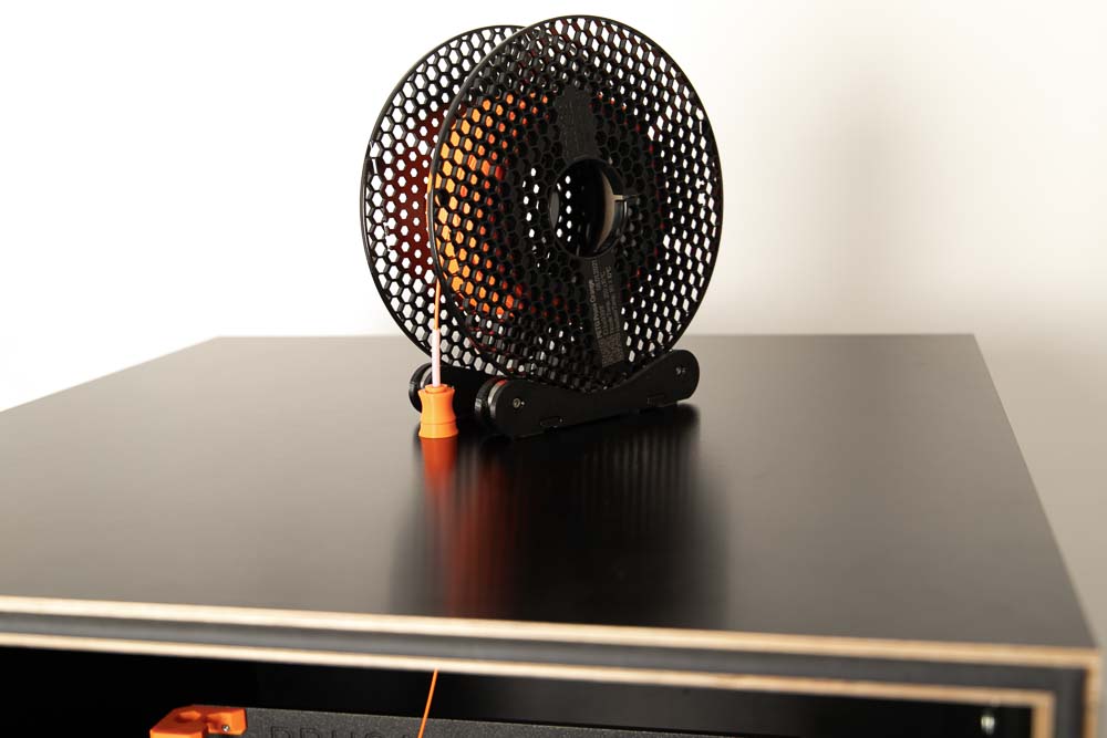
Example 1: Direct Drive Extruder – Filament from above directly from the filament spool
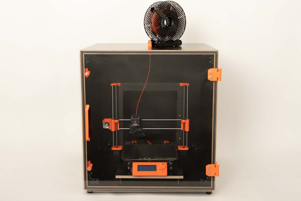
The Prusa i3 MK3 has a Direct Drive extruder and feeds the filament from the top by default.
Shown here with a Variant A filament feedthrough from above. The filament comes directly from the spool, which sits on a Prusa Mini Spool Holder.
Example 2: Direct Drive Extruder – Filament coupled from the side using a supply tube and redirected with a pulley to the extruder
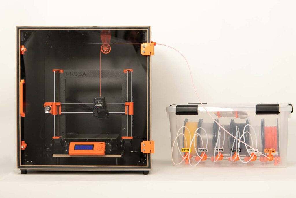
If several 3D printer enclosures are to be stacked or if the 3D printer is to be supplied with filament from the side, a side filament feedthrough is the way to go. The filament is guided down to the printer by means of a pulley. In this case, a PTFE tube deliver the filament from the DIY filament dry box.
Shown here with a Variant B filament feedthrough from the side and with a filament deflection pulley.
Example 3: Bowden extruder – Filament coupled from the side using a PTFE supply tube
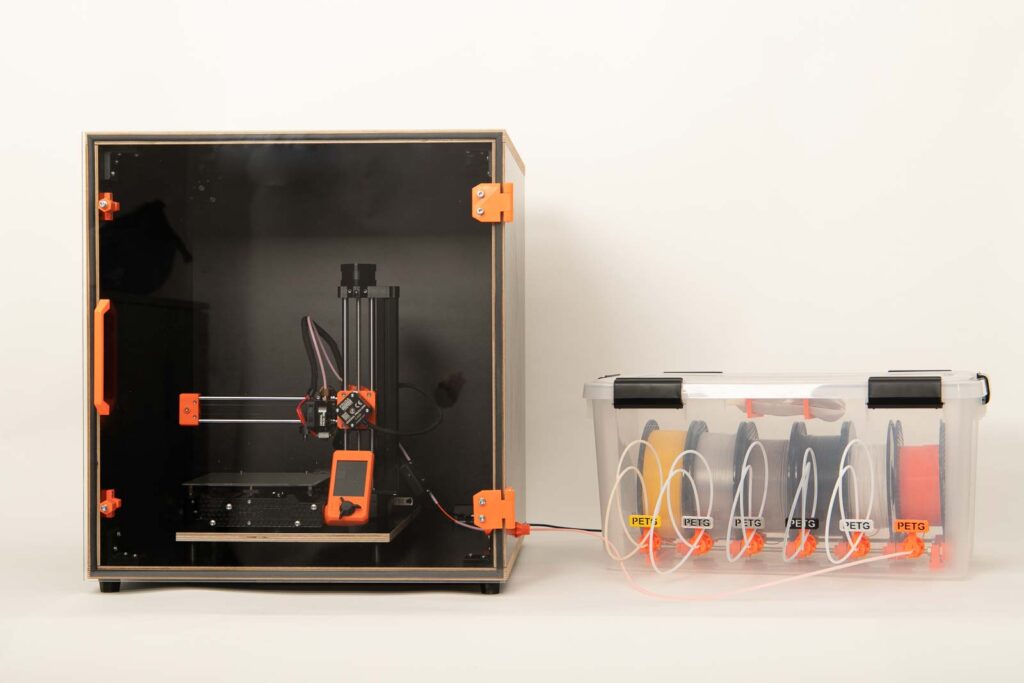
The Prusa Mini has a Bowden extruder with the filament being fed in on the right side. Important, as the – to be printed – part height (Z-axis) increases, the extruder moves further and further upwards.
In this case, a Variant C filament feedthrough from the side is used. Here a PTFE tube is directly connected to a DIY filament dry box. In addition, the flexibility of the short piece of tubing in the enclosure ensures that the change in height of the feed is compensated and the filament is redirected well.
If you don’t have a filament box or PTFE tube to be connected, Variant A can of course also be installed in the last example (Bowden extruder) and the filament comes directly from a filament spool that stands on a spool holder on the side of the enclosure.
The examples show just a few of the possibilities that can be implemented with the included STL files. Before starting the project, it is best to think about the space situation and how the setup of the 3D printer enclosure and filament storage should look like.
All filament feedthrough variants are of course included in the 3D print files of the DIY 3D printer enclosure and are described in detail in Step 10: Filament feedthroughs.
Mark the point for filament passage
Before marking, make clear from where the filament is later to be inserted into the enclosure and how the 3D printer will pull it in.
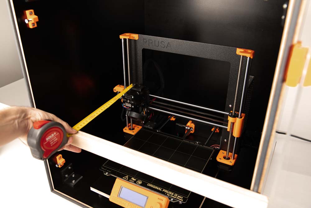
To determine the depth at which the 3D printer’s filament feeder is located, use a wooden bar or a long ruler and a tape measure to determine the distance of the extruder feeder to the front edge of the 3D printer enclosure.
If the filament comes from above and is fed into a direct drive 3D printer, as in Example 1. It is best to position the feedthrough directly in the middle between the Right and Left panels. This way the filament is deflected the least when the extruder moves along the X axis.
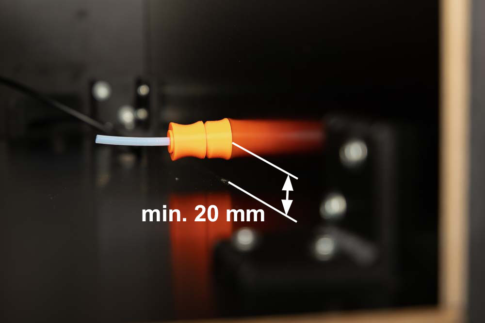
If the feedthrough is drilled at the very bottom or at the top on one side, make sure that there is still enough space left to the top or base of the enclosure interior (at least 20 mm) to install the printed parts.
If the filament is also redirected via the 3D printed pulley, then make sure that the bore is at the same height as the pulley feed-in. The filament must run parallel to the top panel and must be pulled straight through the feedthrough.
Drill the filament feedthrough hole in the 3D printer enclosure
All available filament passages (Variant A, B and C ) require a 10 mm hole in the 3D printer enclosure.
To do this, mark the position of the 3D printer determined in Step 8: Place the 3D printer in the enclosure and remove the 3D printer from the enclosure again.
The drilling example, which is shown below, shows how to make a hole in the Top panel, resulting in a filament passage as shown in Example 1.
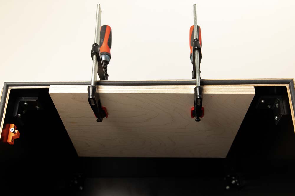
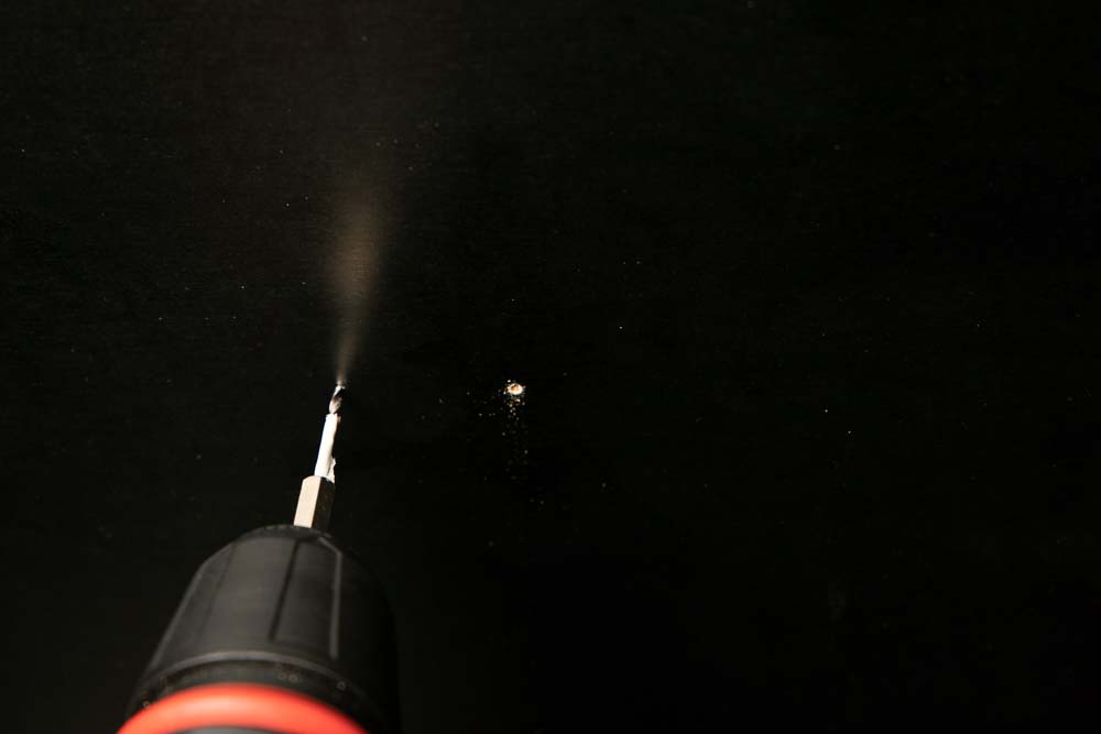
To avoid the wood tearing out at the exit point of the wood drill, it is advisable to fasten a sacrificial piece of scrap wood using bar clamps where the drill later exits.
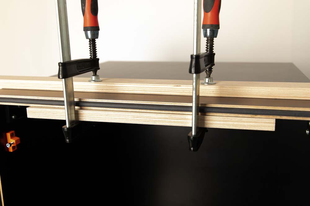
To prevent the bar clamps from leaving marks on the enclosure, place another piece of scrap wood on the outside between the clamps and the enclosure.
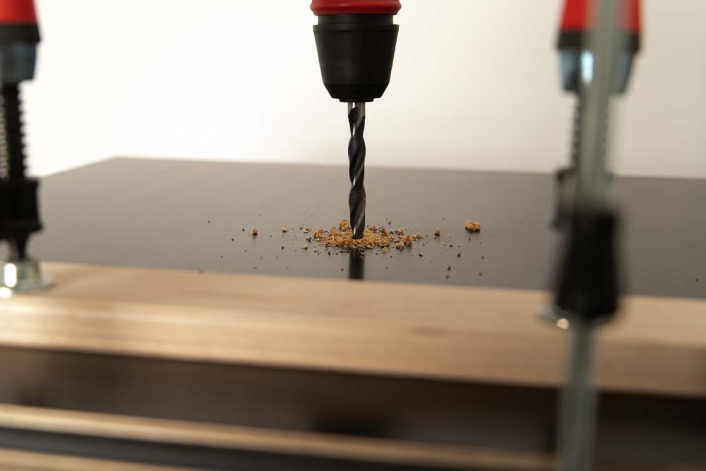
Cordless screwdriver with 10 mm wood drill on the outside of the box when drilling.
Wear safety goggles and watch out for chips coming out. Do not reach into the interior of the 3D printer enclosure with your hand, as there is a high risk of injury if the drill bit exits on the inside!
Clean the hole with some sandpaper and in the next step mount the filament feedthrough.
Closure of unnecessary holes
Does the chosen position of the passage turn out to be unfavorable or has the position of the enclosure or the filament storage changed? No problem, the 10 mm holes in the box can easily be closed with the bore cover included in the 3D print files of the DIY 3D printer enclosure.
Simply print them in the desired color and insert into the redundant holes.
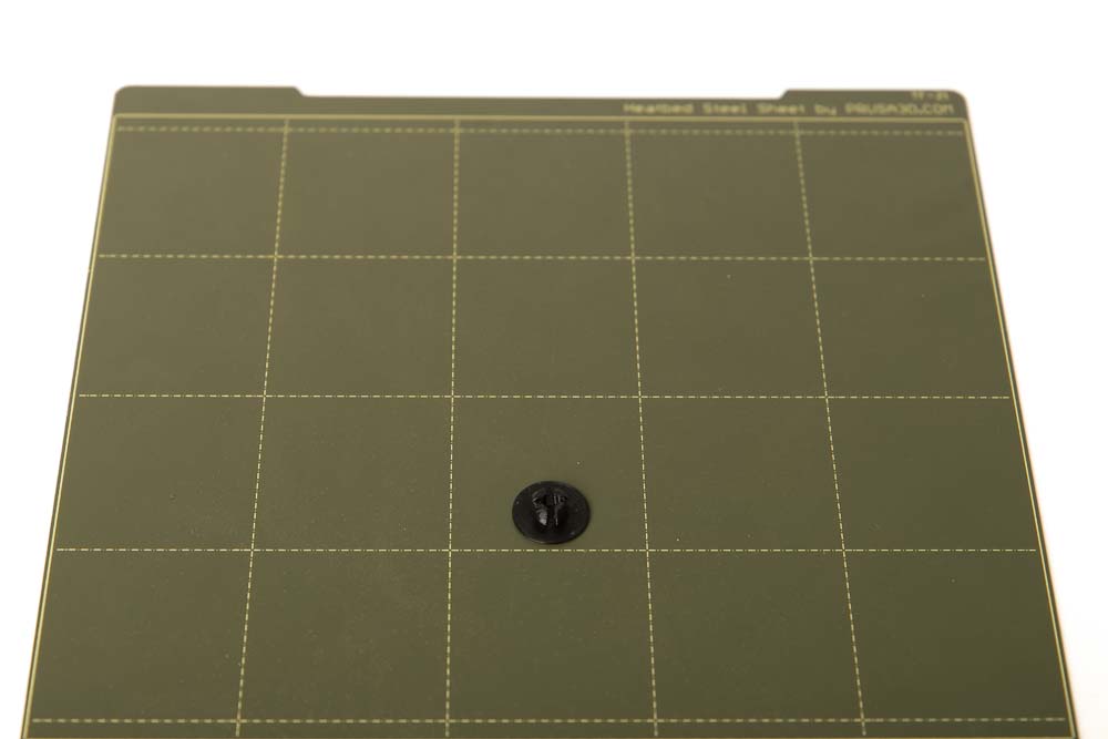
- 1 pc 004500_Bore_Cover
Layer height 0.2 mm and 100% infill (rectangular)
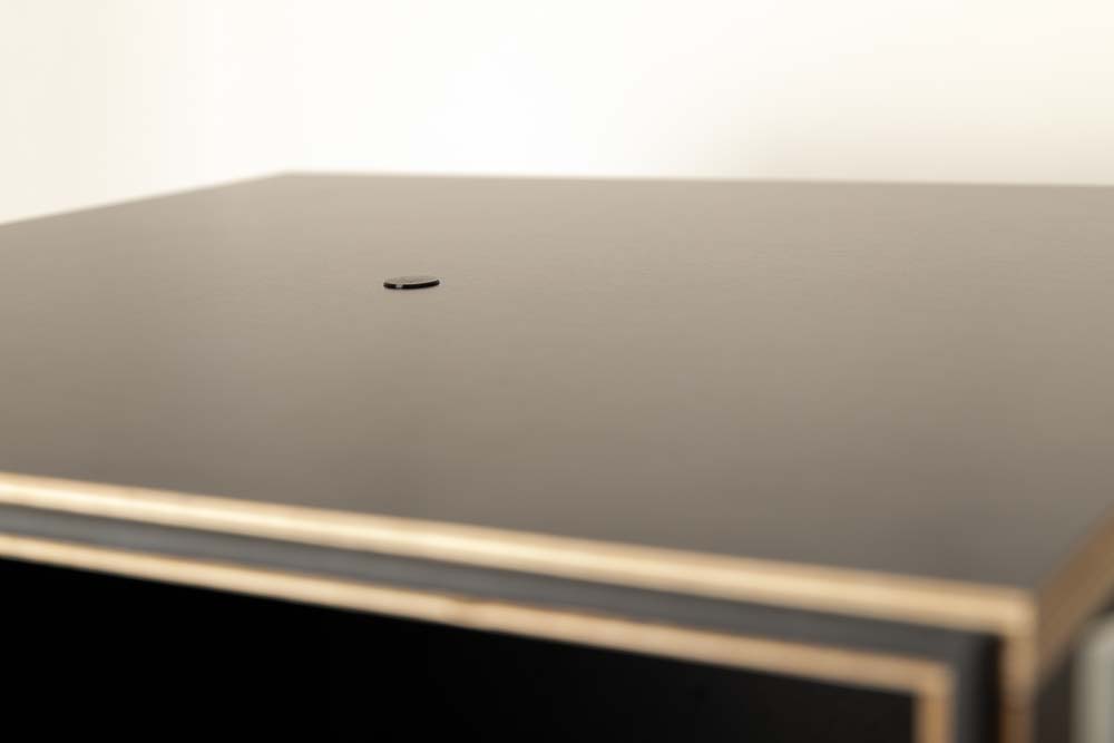
Here a black cover closes a filament feedthrough hole in the enclosure.
Step 10: Filament feedthroughs
If the filament is fed into the enclosure from the outside, there are different components in the included STL files to build different filament feedthroughs. This allows the filament to be easily fed into the self-made enclosure from above or from the side.
Please do not get confused by the many options, Variant A is the standard version you cannot go wrong. If you want something more special, there are also Variants B and C. A filament supply tube can be connected and disconnected directly to these feedthroughs, for example the supply tube from the DIY filament dry box.
Since all feedthroughs require a 10 mm hole in the 3D printer enclosure, you can easily switch between the variants later.
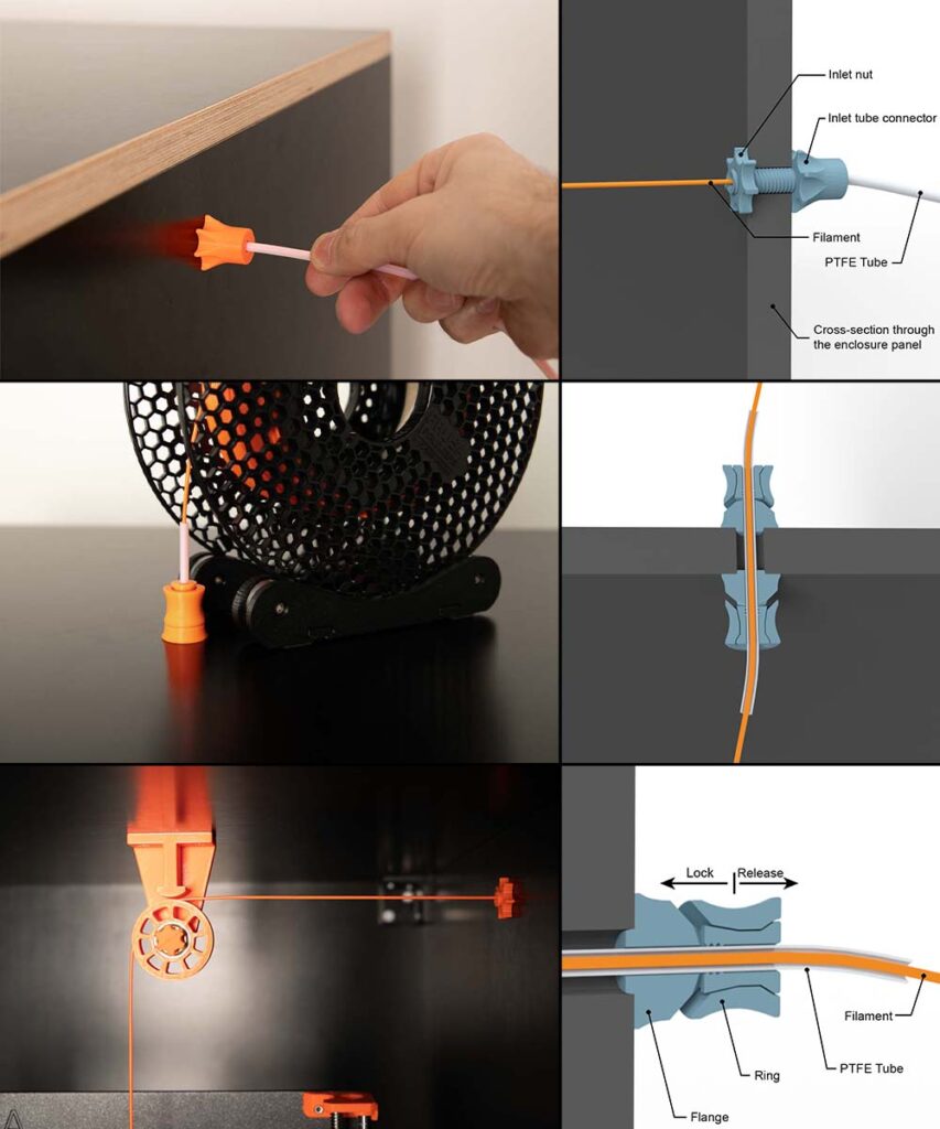
Variant A – standard version
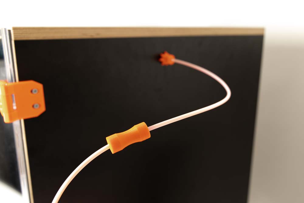
A PTFE tube is used as a feedthrough. A short PTFE tube is fixed using two tube clamps. Very simple solution consisting of only three components. The PTFE tube remains flexible on the inside and outside and guides the 3D printing filament, even if the feed or pull off is not precisely straight.
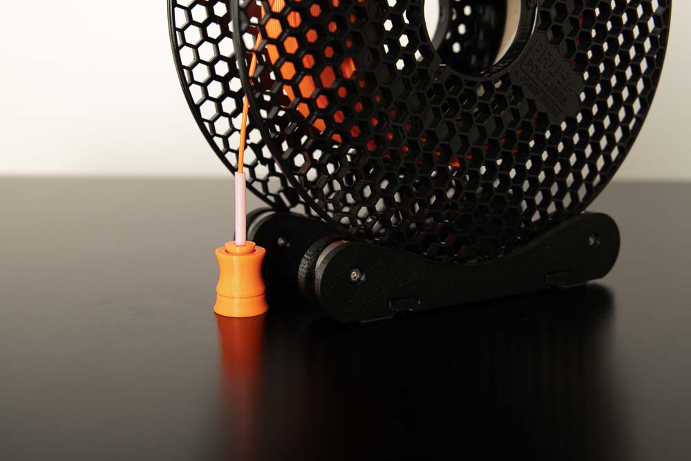
Here, a roll of filament is stored on the outside and the filament is fed in through the inlet.
The following illustrations show the passage in the enclosure, for better visibility with a cross-section through the wall of the 3D printer enclosure and then once with an additional section through the feedthrough.
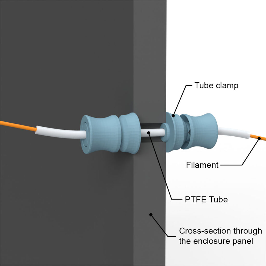
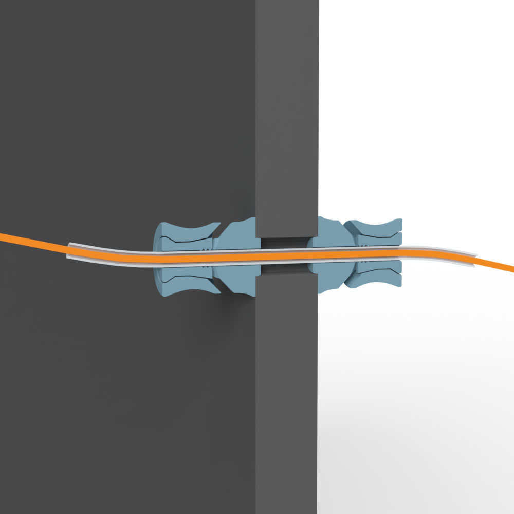
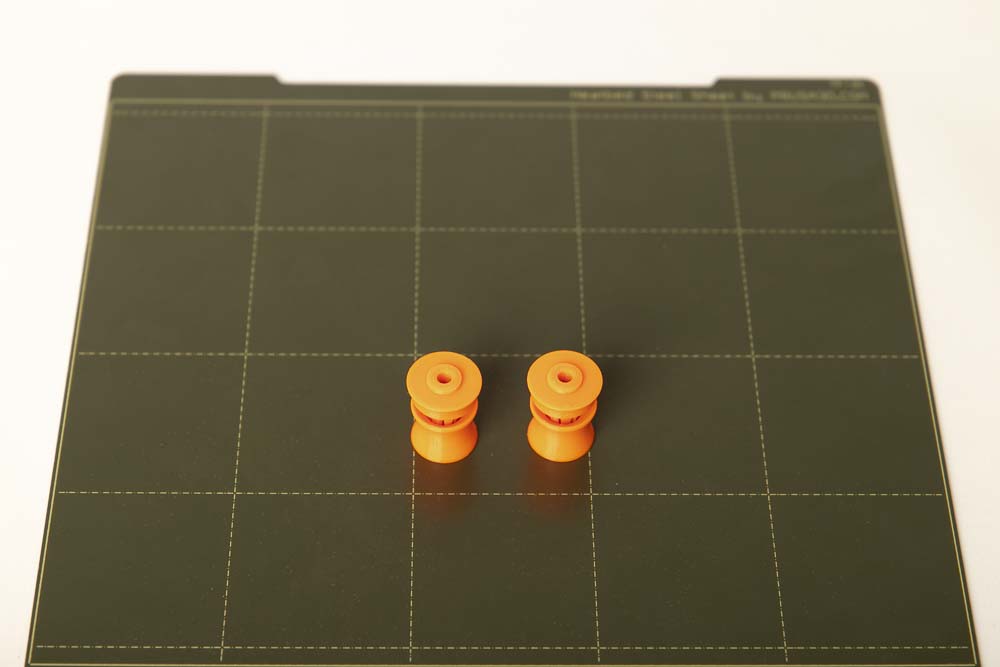
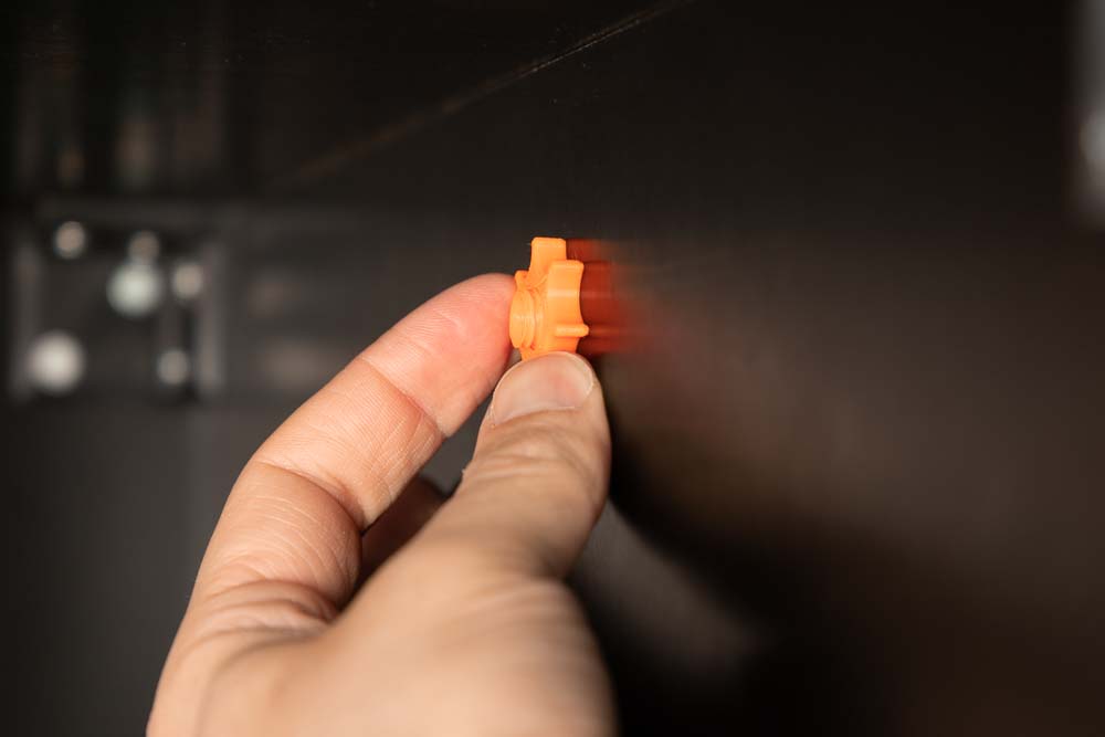
How the tube clamps work
The tube clamps work like a quick-release fastener. The inserted PTFE tube is clamped or released by means of a movable ring, which is directly printed with the part.
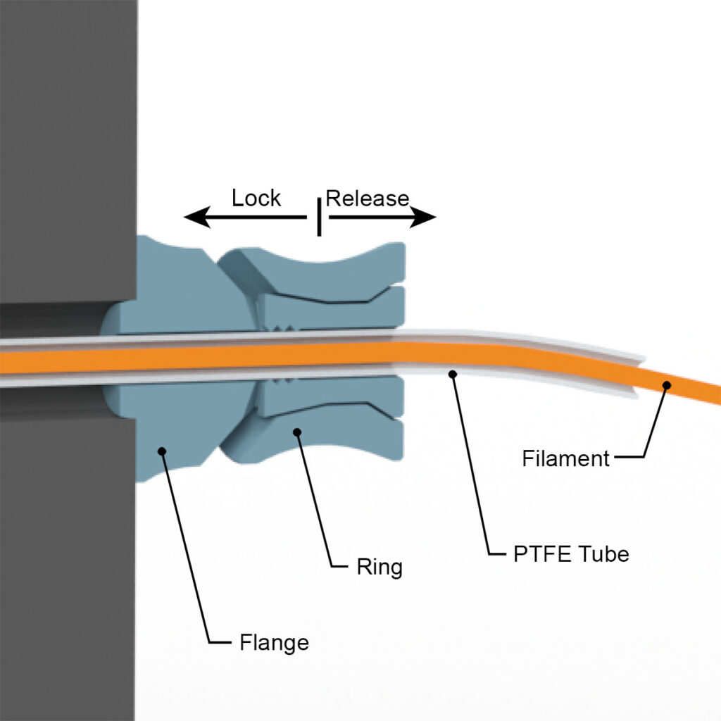
The 4 or 5 mm (outer diameter) PTFE tube is pushed through and if it is to be fixed, the ring is pressed in the direction of the flange. As a result, the ring presses four grippers inwards via a cone, which fix the tube in this position.
When designing, care was taken to make the part as easy to print as possible. 3D printing offers fantastic possibilities here, so each clamp comes complete with the installed ring from the 3D printer, without any assembly. 3D print it just like a simple part, without any support material or structures.
Required purchased parts
- approx. 12 cm (5″) PTFE tube OD4 ID3 – or PTFE tube with OD5 ID3 or OD5 ID4
Required 3D printed parts
- 2 pcs 004600_Tube_Clamp_OD#
OD depending on the used PTFE tube
- Outer diameter 4 mm with OD4 or
- Outer diameter 5 mm with OD5
Layer height 0.2 mm and 100% infill (rectangular)
Assembly of Variant A
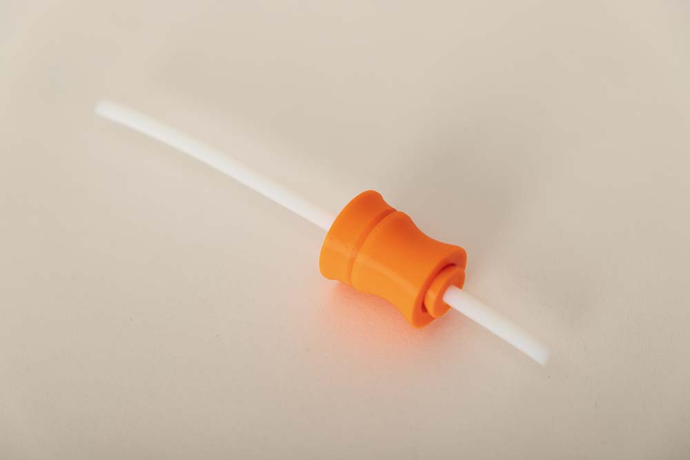
When assembling, simply position a tube clamp on the PTFE hose so that approx. 3 cm hose protrudes. Then hold the flange and press the ring against the flange to fix the tube in the clamp.
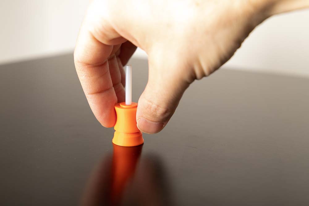
Then push the tube with the fixed clamp through the 10 mm hole from the inside to the outside. Hold the ring of the clamp inside and pull on the second tube clamp from the outside. When the flanges of the clamps are flush with the wooden panel, then press the ring towards the panel and thus fix the PTFE tube.
After installation of the PTFE tube, check if the tube is fixed and cannot slip.
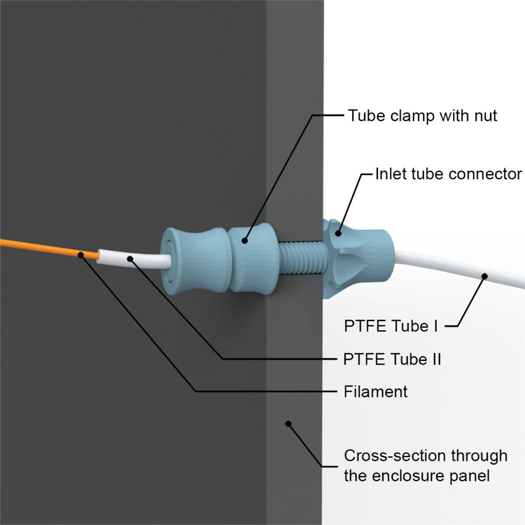
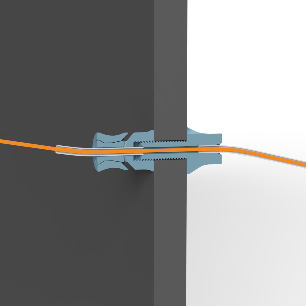
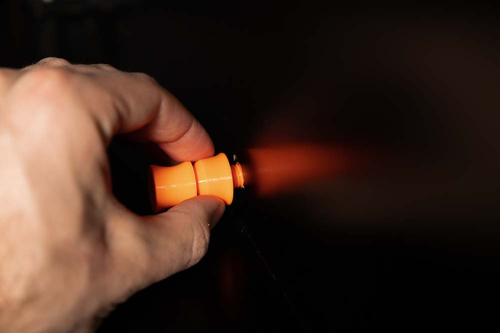
Variant B – PTFE tube can be attached and detached
With this variant, a filament-feeding PTFE hose can be easily plugged in on the outside of the enclosure. For example, if you have already built a filament dry box with long supply tubes, these can be attached directly to the tube connector. The PTFE tube can be easily plugged in and unplugged through the conical opening.
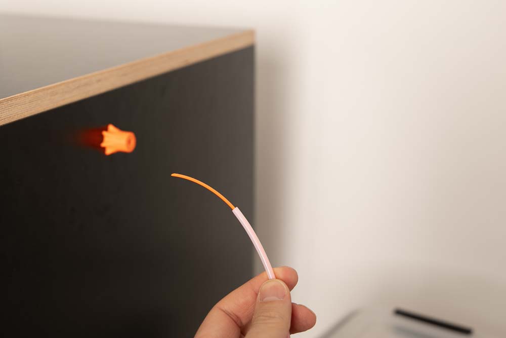
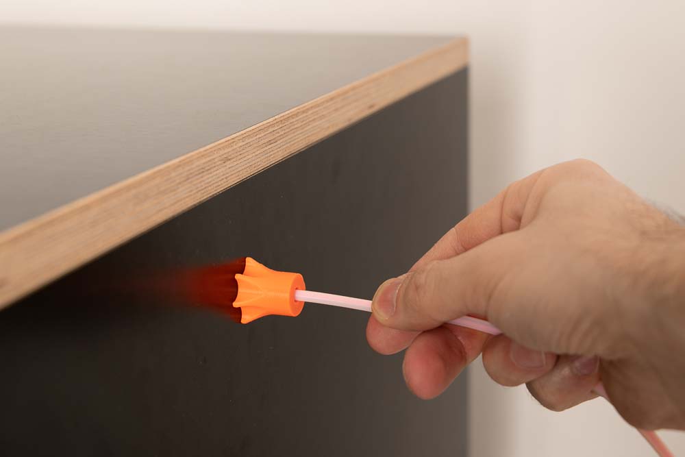
Simply let a little filament protrude over the tube, then thread it into the connector and push the tube in place. The inner cone in the connector holds the tube, after printing it can be easily removed by pulling.
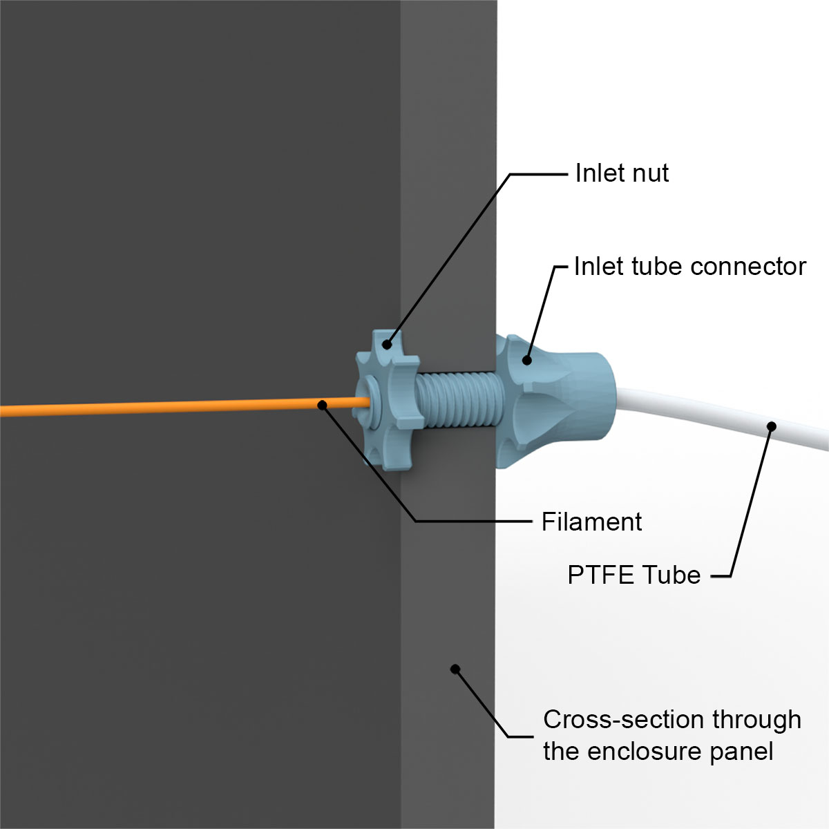
Here are two more technical illustrations with a section through the enclosure and through the tube connector, showing the functionality and details of Variant B. The 3D print files of the DIY 3D printer enclosure contain the STL files for connectors with different thread lengths. So different wooden panel thicknesses from 10 to 35 mm can be used when building the 3D printer enclosure.
Since the filament is not guided by a flexible PTFE tube on the inside, it must be pulled off as straight as possible in this variant to avoid wearing down the 3D printed part.
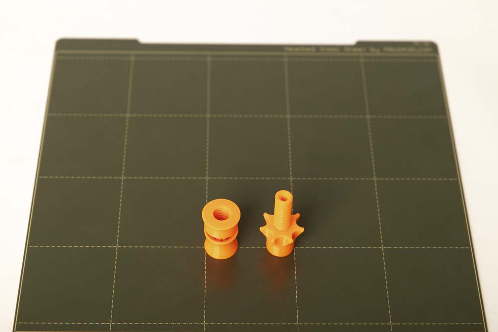
Required 3D printed parts
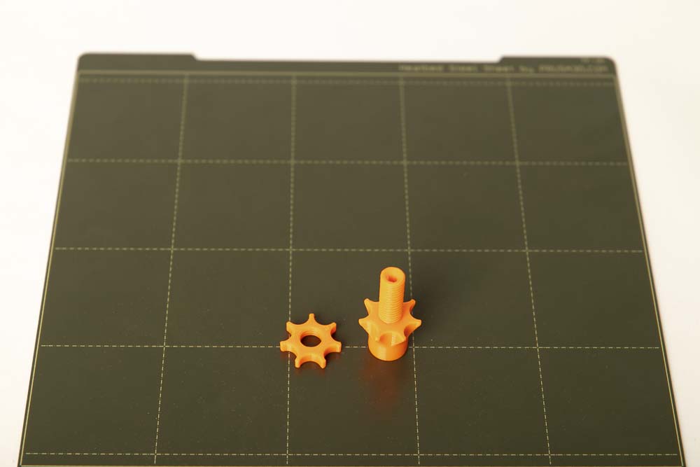
- 1 pc 004300_Inlet_Tube_Connector_OD#_L##
- 1 pc 004400_Inlet_Nut
OD depending on the used PTFE tube
- Outer diameter 4 mm with OD4 or
- Outer diameter 5 mm with OD5
L depending on the thickness of the wooden panels
- L= 20 with a thickness of 10 – 15 mm
- L= 25 with a thickness of 16 – 20 mm
- L= 30 with a thickness of 21 – 25 mm
- L= 35 with a thickness of 26 – 30 mm
- L= 40 with a thickness of 31 – 35 mm
Layer height 0.2 mm and 100% infill (rectangular)
Assembly of Variant B
The assembly is very simple, insert the Inlet_Tube_Connector from the outside through the 10 mm hole and secure it with the Inlet_Nut on the inside.
Do not tighten the nut with a tool or too firmly, to avoid that the 3D printed parts are damaged.
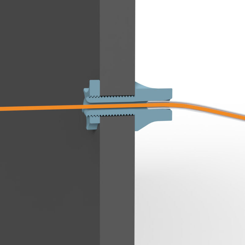
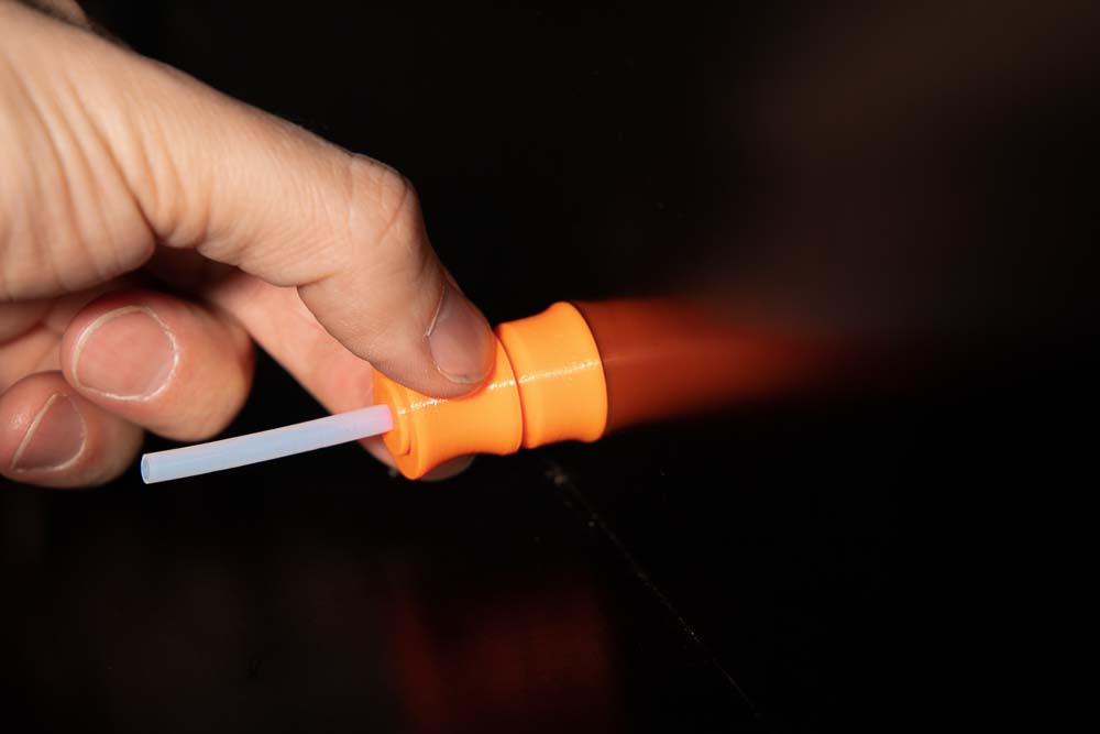
Variant C – PTFE tube connector with flexible deflection inside
This variant is a combination of Variants A and B. If a filament deflection is required at the inside of the enclosure, a short piece of PTFE tube can be fixed here using the inner Tube_Clamp_with_Thread instead of the Inlet_Nut. This ensures a smooth deflection of the filament before reaching the 3D printer. As with Variant B, a PTFE tube can be easily attached and detached on the outside of the enclosure.
Required purchased parts
- approx. 6 cm (2-1/2″) PTFE tube OD4 ID3 – or PTFE tube OD5 ID3 or OD5 ID4
Required 3D printed parts
- 1 pc 004300_Inlet_Tube_Connector_OD#_L##
- 1 pc 004700_Tube_Clamp_with_Thread_OD#
OD depending on the used PTFE tube
- Outer diameter 4 mm with OD4 or
- Outer diameter 5 mm with OD5
L depending on the thickness of the wooden panels
- L= 20 with a thickness of 10 – 15 mm
- L= 25 with a thickness of 16 – 20 mm
- L= 30 with a thickness of 21 – 25 mm
- L= 35 with a thickness of 26 – 30 mm
- L= 40 with a thickness of 31 – 35 mm
Layer height 0.2 mm and 100% infill (rectangular)
Assembly of Variant C
Insert the Inlet_Tube_Connector from the outside through the 10 mm hole and secure it on the inside with the Tube_Clamp_with_Thread.
Do not tighten the Tube_Clamp_with_Thread with a tool or too firmly, to avoid that the 3D printed parts are damaged.
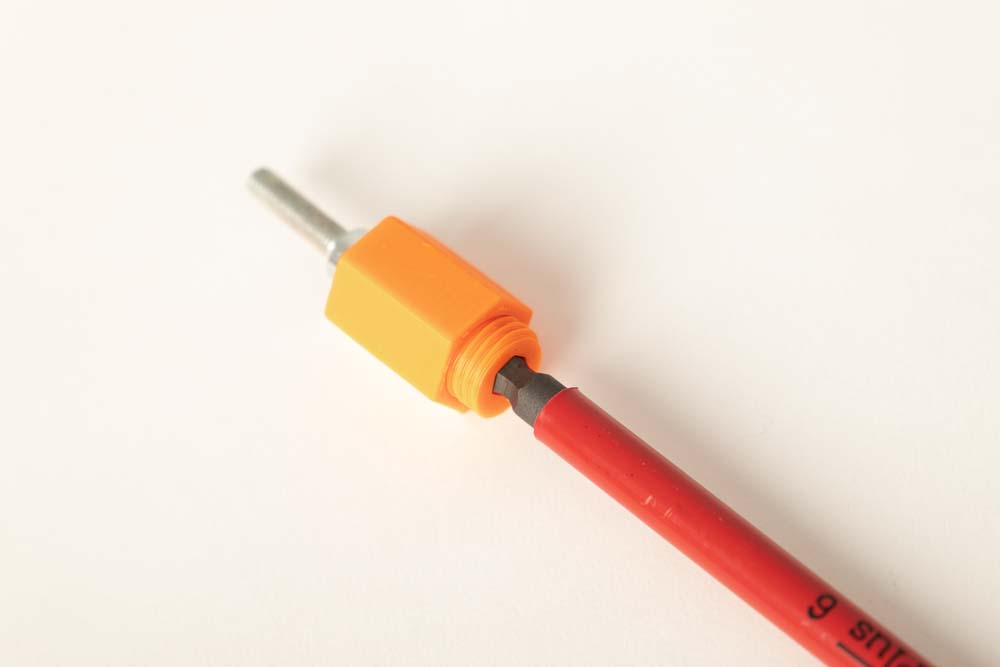
Insert the short piece of PTFE tube into the Tube_Clamp_with_Thread and push it as far as it will go in. Then push the ring in the direction of the enclosure wall and thereby secure the tube.
Installation of the pulley and its holder in the 3D printer box
Additionally, a filament redirection pulley and its holder are included in the 3D print files. These 3D printing parts help when, for example, the filament is fed into the enclosure from the side but it has then to be fed into the 3D printer extruder from above.
The pulley is mounted in the enclosure and feeds the filament into the 3D printer extruder. For example, here the Prusa i3 MK3 gets the filament from above directly into its extruder.
Required purchased parts
- 1 pc Ball bearing 608
- 2 pcs Wood screws #7 x 3/4″ flat head (corresp. 4×20 mm)
Required 3D printed parts
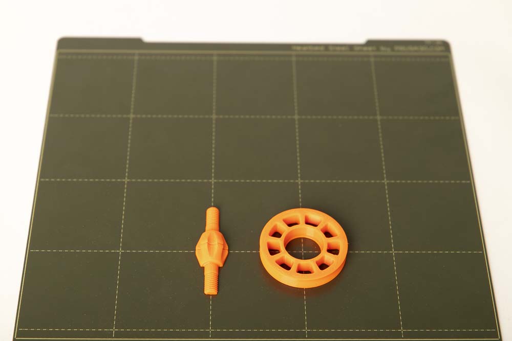
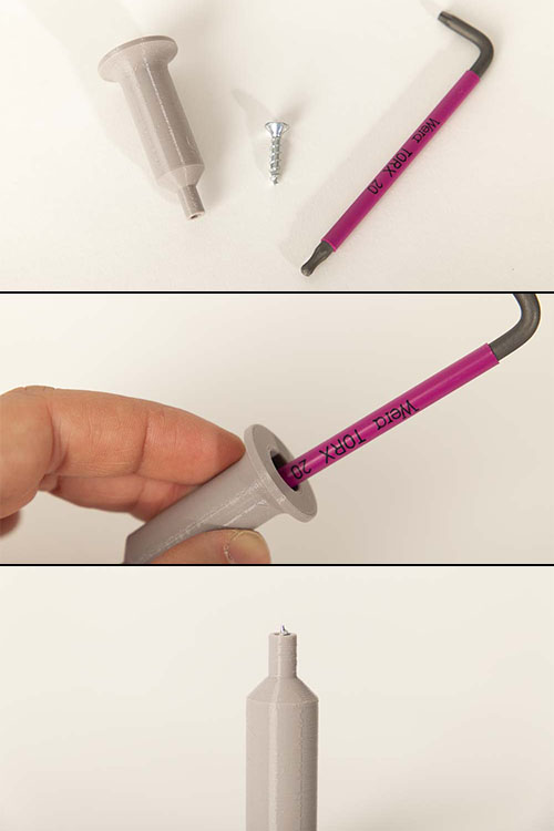
- 1 pc 002300_Pulley
- 1 pc 002400_Screw
Layer height 0.2 mm and 100% infill (rectangular)
- 1 pc 004200_Pulley_Holder_A##
Depending on the distance between the center of filament feedthrough and the inner enclosure wall, the height of the pulley holder results in the distance A= 10, 20, 30, 40, 50, 60 mm.
Layer height 0.2 mm and 20% infill (rectangular)
Optional for easier assembly and disassembly of the ball bearing in the pulley.
- 1 pc 000400_Tool_Bearing_Press_In
- 1 pc 000500_Tool_Bearing_Press_Out
- 1 pc 000600_Tool_Bearing_Press_Counter
Layer height 0.2 mm and 100% infill (rectangular)
To press the ball bearing into the pulley, print out the tools provided. This makes it much easier to press in the bearing and, if necessary, to press it out again.
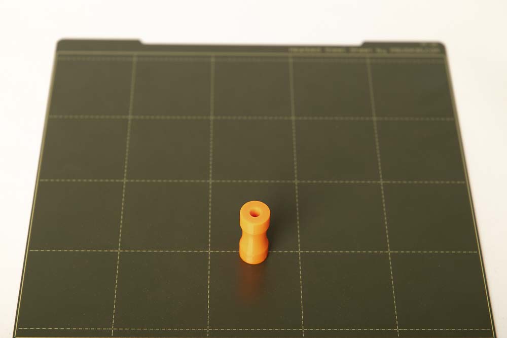
Assembling the 3D printed pulley
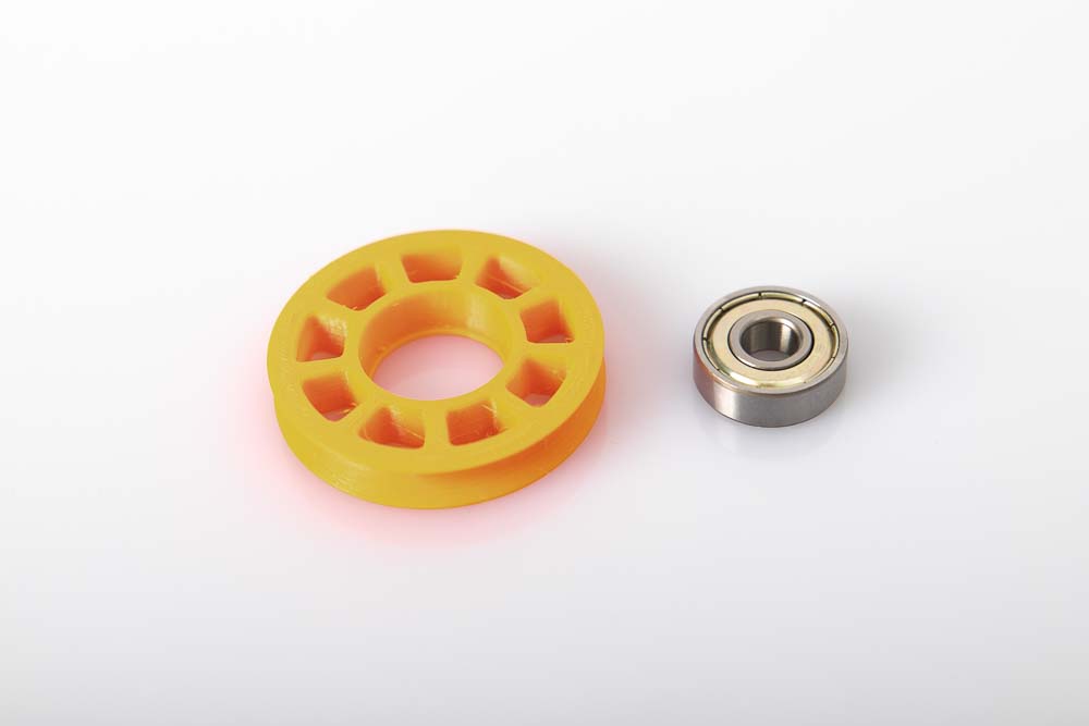
The pulley has an opening for the 608 ball bearing. Check it for filament residue and clean if necessary.
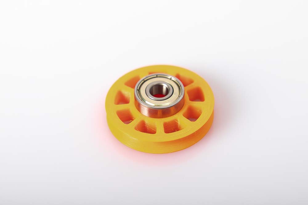
Insert the 608 ball bearing on the side of the pulley that has the wider opening.
Attach a second ball bearing as a press stamp or the 3D printed Tool_Bearing_Press_In aid and press firmly until the ball bearing is pressed completely against the stop in the pulley.
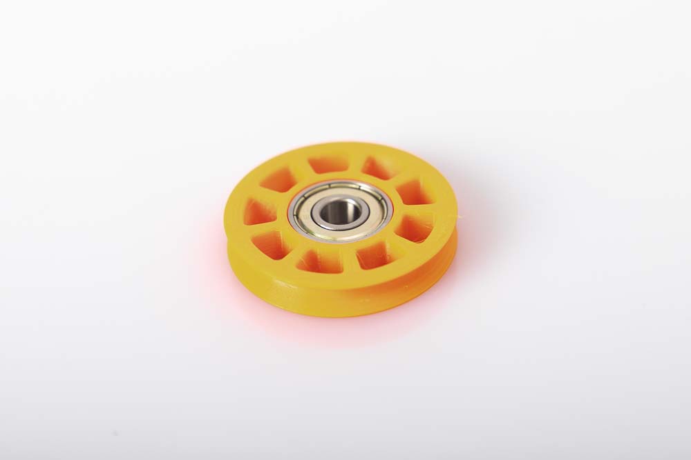
The ball bearing should be fully pressed in, parallel to the pulley. Check at the backside of the pully if the whole bearing circumference is pressed against the stop (the small step in the bore of the pulley).
The ball bearing must sit securely and firmly, as well as parallel and not skew in the deflection pulley! This is important so that the pulley does not block later.
If the ball bearing is too hard or too easy to press into the pulley, it is best to scale the pulley STL file in the slicer a little (0.5 to 1%) in the X and Y direction and then reprint it.
If the ball bearing has to be removed from the pulley, the Tool_Bearing_Press_Out and Tool_Bearing_Press_Counter can be used. How this works is explained in the instructions for the filament dry box in the chapter Pressing a 608 ball bearing out of a pulley.
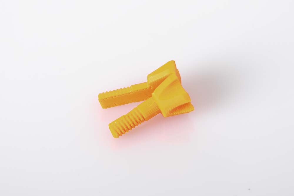
Assembling the split screw
To print a screw that has more strength, it is divided into two and designed to be folded. As a result, the screw axis can be printed in the X or Y direction, and thus has a higher strength than in the Z direction. The assembly and installation do not change much. The screw only needs to be folded before installation. Optionally, the two halves can also be glued together.
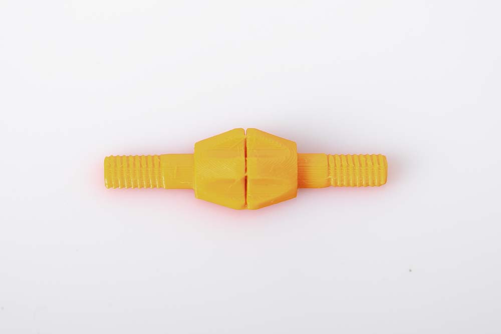
The screw as it is removed from the print bed. The two halves of the screw are connected with a thin layer.
Simply fold the two halves of the screw together. The screw can thus be screwed directly into the thread of the pulley holder.
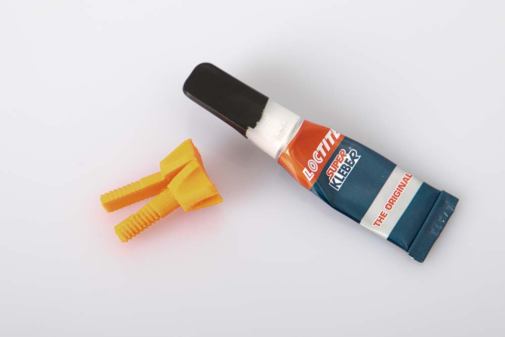
Optionally, the two halves of the screw can also be glued together. Simply use super glue and apply a thin layer on one side. Then briefly press the halves together until the adhesive has hardened.
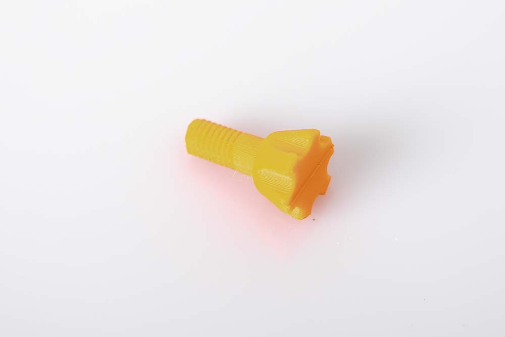
The finished glued or folded screw.
Installation of the pulley on the deflection pulley holder
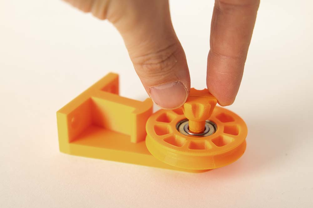
Screw the prepared pulley with the screw into the pulley holder and tighten.
For installation in the 3D printer enclosure, remove the pulley again and only reinstall it after mounting the holder in the enclosure.
Tighten the screw firmly, but do not use tools to avoid damaging the 3D printed threads.
Installing the pulley holder in the DIY 3D printer box
Place the assembled pulley holder in the 3D printer enclosure in such a way that the filament is fed as straight as possible to the pulley and the 3D printer can pull it off without any problems. It is best to test with filament and mark the appropriate position with a pen. Then unscrew the deflection pulley from the pulley holder and mark the required pilot holes.
Pre-drill with a 2 mm wood drill (approx. 10 mm deep) and then fasten the holder with two wood screws. Finally, mount the pulley again with the 3D printed screw.
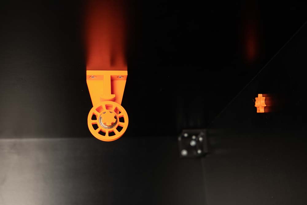
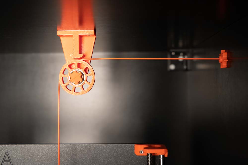
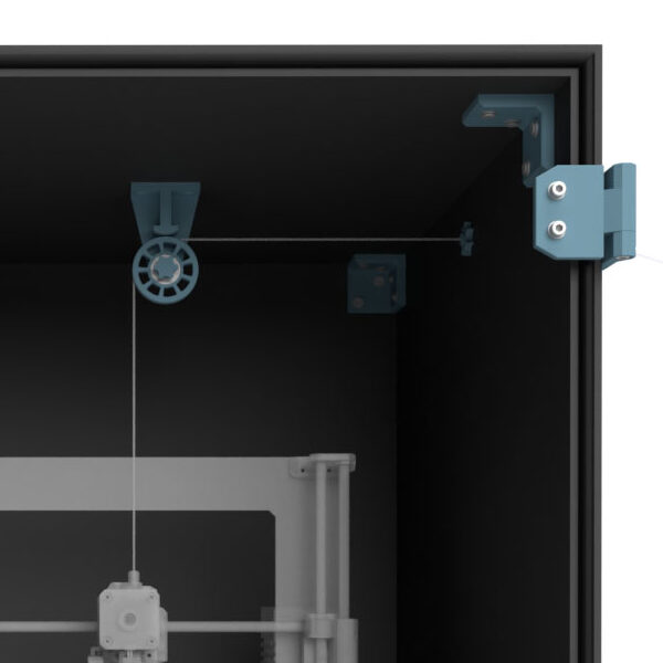
Fully assembled redirection pulley, the filament is guided through a feedthrough Variant B from the right side into the enclosure. Then the filament is redirected downwards via the deflection pulley to the 3D printer.
Afterwards, check if the delivery and pulling of the filament work smoothly.
Addition: 3D printed coupling to extend the filament supply tubes
As an additional STL file there is a coupling for PTFE tubes with an outside diameter of 4 mm (OD4) and 5 mm (OD5). If the filament supply hose need to be extended, simply couple another piece of tube in between.
Required 3D printed parts
- 1 pc 004800_Tube_Coupling_OD#
Layer height 0.2 mm and 100% infill (rectangular)
OD depending on the used PTFE tube
- Outer diameter 4 mm with OD4 or
- Outer diameter 5 mm with OD5
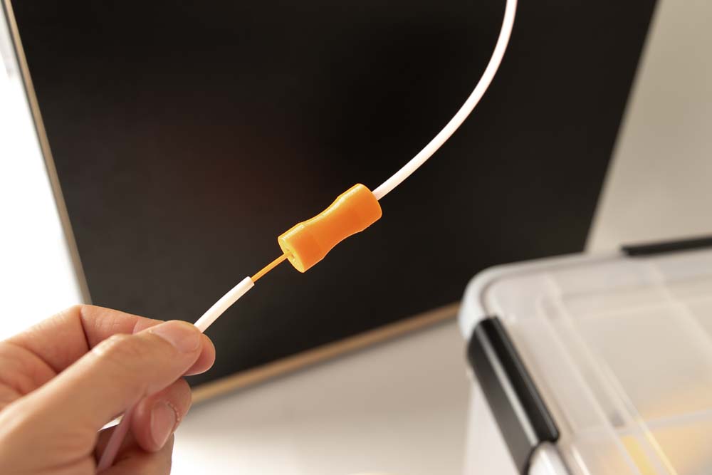
Simply connect two PTFE supply hoses using a 3D printed coupling. Don’t forget to push the filament all way through to the end of the tubes first.
The 3D printed coupling makes it easy to cover longer distances from for example the filament dry box to the 3D printer enclosure.
Always test whether the filament can be pulled through the supply tubes with only little force. If this is not the case, reduce the overall length of the hoses or choose a different route. Choose the inner diameter of the tubes as large as possible so that the filament in it generates as little friction as possible.
The filament must always be easy to pull through the PTFE supply tubes. If it is too hard to pull or stuck, it may cause the 3D printer to malfunction.
After installing the filament feedthrough, position the 3D printer back in place.
Congratulations! The 3D printer enclosure is finished, only the final function tests in the next step are missing.
Step 11: Test run for the self-made 3D printer enclosure
At the end of the assembly a final test run is necessary. Check if everything is working and if the 3D printer can do its job well.
Carry out the test run and the test print according to the instructions, otherwise the 3D printer may malfunction later.
Preparation for the test
Before the test, be sure to read and follow the operating manual of the DIY 3D printer enclosure and the safety guidelines given there!
Position a filament roll on your spool holder and thread it through the filament passage and, if installed, the deflection pully.
Check filament for ease of movement
Check if the filament runs smooth and can be pulled in by the 3D printer extruder easy. To do this, guide the filament to the 3D printer filament feeder by hand and test how difficult or easy it is to move the filament. If this only works with great effort, then check the individual deflection points, passages and tubes used. Each deflection of the filament creates some friction. The following things can help to increase ease of movement:
- Produce the unwinding device (spool holder) too much friction? Rely on ball-bearing unrolling devices that have a very low rolling resistance.
- Is the supplying PTFE tube too long or is it often deflected? Shorten the tube to the shortest possible length and route the tube as straight as possible. Try to use as few deflections as possible.
- Is the inner diameter of the PTFE tube too small? Always choose the inner diameter at least 1 mm larger than the filament diameter. This means using a 3 mm inner diameter for a 1.75 mm filament and a 4 mm inner diameter for a 2.85 mm filament.
- With the filament implementation of Variant B, the filament may be deflected too much when it exits the interior of the enclosure and touches the 3D printed Inlet_Tube_Connector. Either change the position of the feedthrough or convert to Variant C.
Pull and move the filament from the filament spool to just before the extruder, then load the filament into the 3D printer’s extruder.
Test of all 3D printer axes
Check the position of the 3D printer in the enclosure again.
Carry out a homing of all axes, paying attention to whether the moving parts of the 3D printer are touching the enclosure or any cables. If necessary, correct the position of the 3D printer or the cable routing.
Then move all axes individually to the maximum position using the 3D printer control and again pay attention to possible contact points and correct them if necessary.
Also observe the filament during this test, if it is bent or deflected too much, the position of the feedthrough or pulley may have to be changed, or the feedthrough variant changed.
Test print under observation
After checking the filament feed and the axes movement, a test print under observation follows to check everything again under normal printing conditions.
Choose any component, preferably a very large 3D printed part, or place some small parts at the outer corners of the print bed. As a result, all extreme positions of the printer are approached. When printing, make sure that everything runs smoothly and that no cables or enclosure walls are touched. Also check if the 3D printer changes its position inside the enclosure during printing due to any vibrations. If that’s the case, use some double-sided tape or rubber anti-vibration feet to increase grip.
If a larger part than the one in this test is printed later, only print under close observation to be able to quickly correct any problems.
If the 3D printer is later removed and reinstalled, slightly modified or another 3D printer is operated in the enclosure, then carry out the test runs and test prints again.
Congratulations! Your DIY 3D printer enclosure is fully assembled and adjusted!
Before starting up, be sure to read and follow the operating manual of the DIY 3D printer enclosure and the safety guidelines given there!
Disclaimer
The instructions and the associated files are an inspiration of Ingenieurbüro Dr. Janko GmbH to build this project yourself. Since Ingenieurbüro Dr. Janko GmbH has no way of checking and influencing the required quality of the printed components and purchased parts as well as the quality of the assembly and the correct functioning of the project or if any inadmissible changes and modifications to the project has been made, Ingenieurbüro Dr. Janko GmbH accepts no liability for functionality, stability or damage incurred by the project.
0 Comments