

Instead of placeing your filament on top of your 3D printer, you want to put it next to it and feed it sideways, or are you building a DIY filament dry box or a 3D printer case?
With 3D printers with Direct Drive Extruders, such as the Prusa i3 MK3, the filament always has to be fed in from above. Here is the perfect solution for 3D printers of this type: the 3D printed filament guide with pulley.
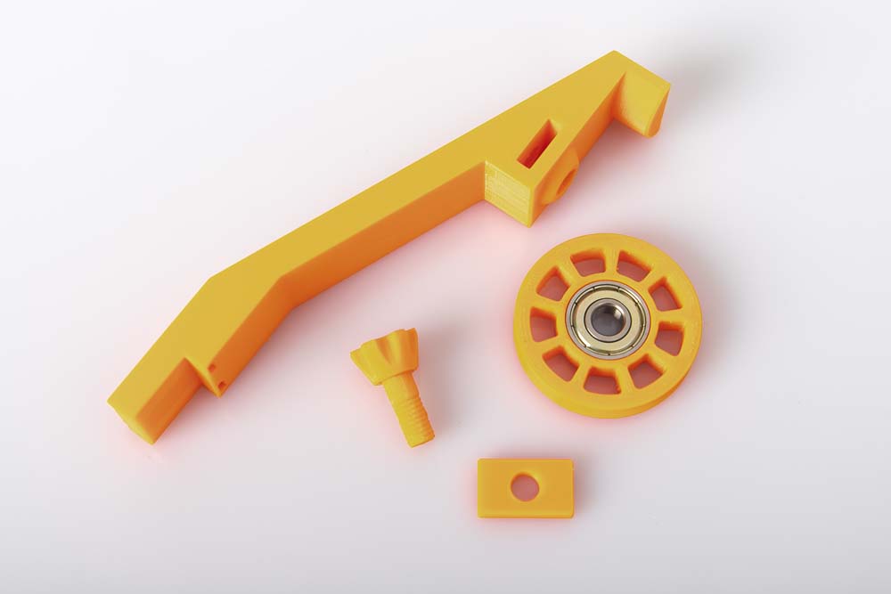
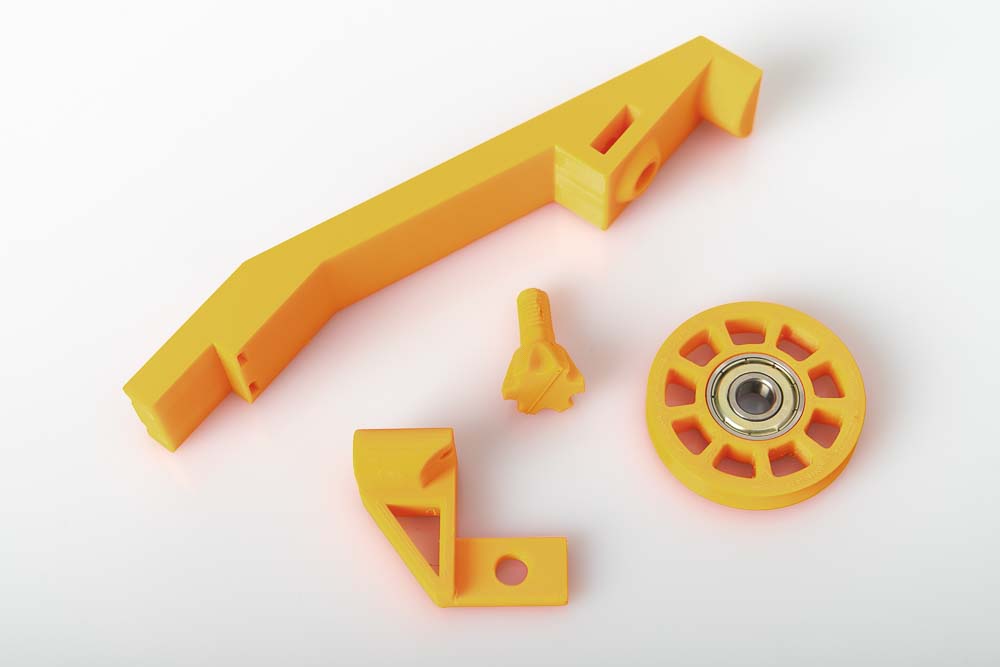
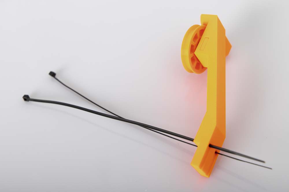
Simply mounted on the top crossbeam and the filament is safely and reliably redirected to your 3D printer. The large pulley ensures that even brittle filaments are not bent too much. Only the 3D print files of the filament guide with pulley from the shop, two zip ties, and a ball bearing are required.
The article contains affiliate links / advertising links, these are marked with an asterisk (*). If you make a purchase through these links, I may receive a commission at no additional cost to you.
Setting up the filament system on your 3D printer
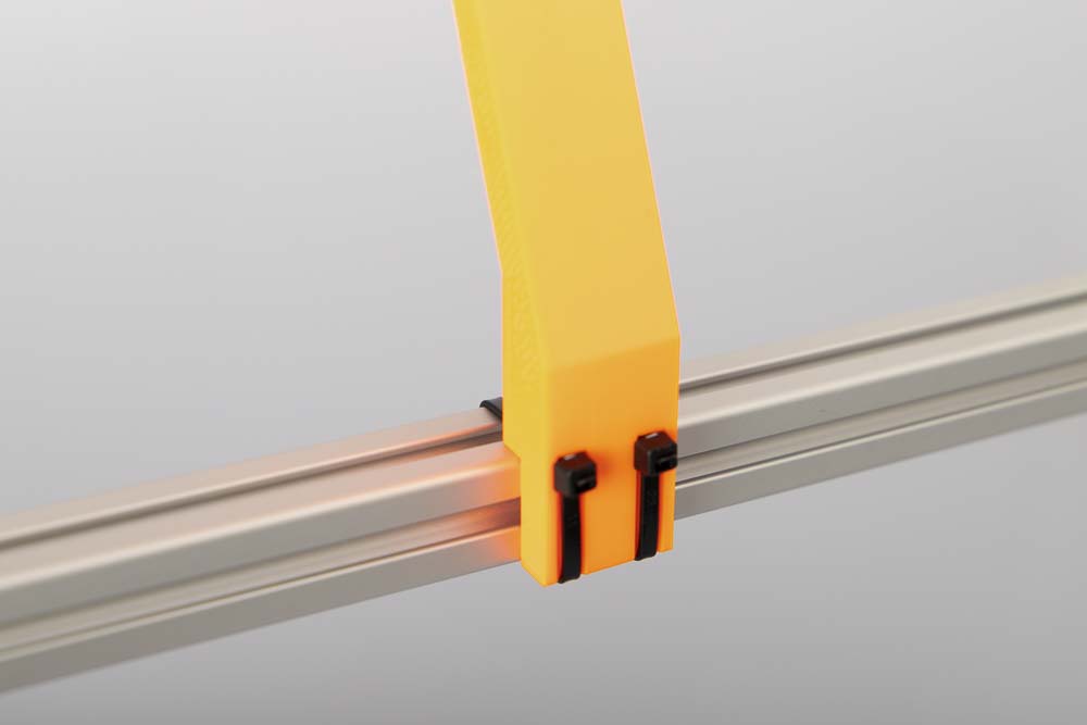
Thanks to the simple and flexible installation with zip ties, the arm fits on a wide variety of crossbeams from different 3D printers, regardless of whether they have a flat or rectangular profile cross section.
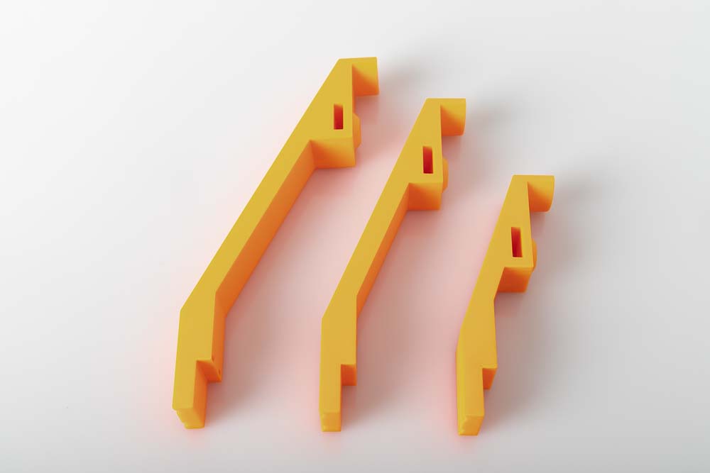
The 3D print files include many differently sized arms and different connection options for the filament.
Find the right filament guiding arm for your 3D printer
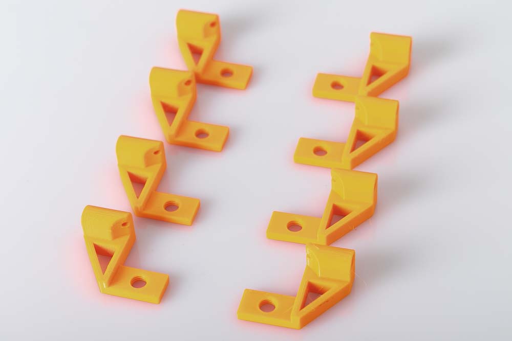
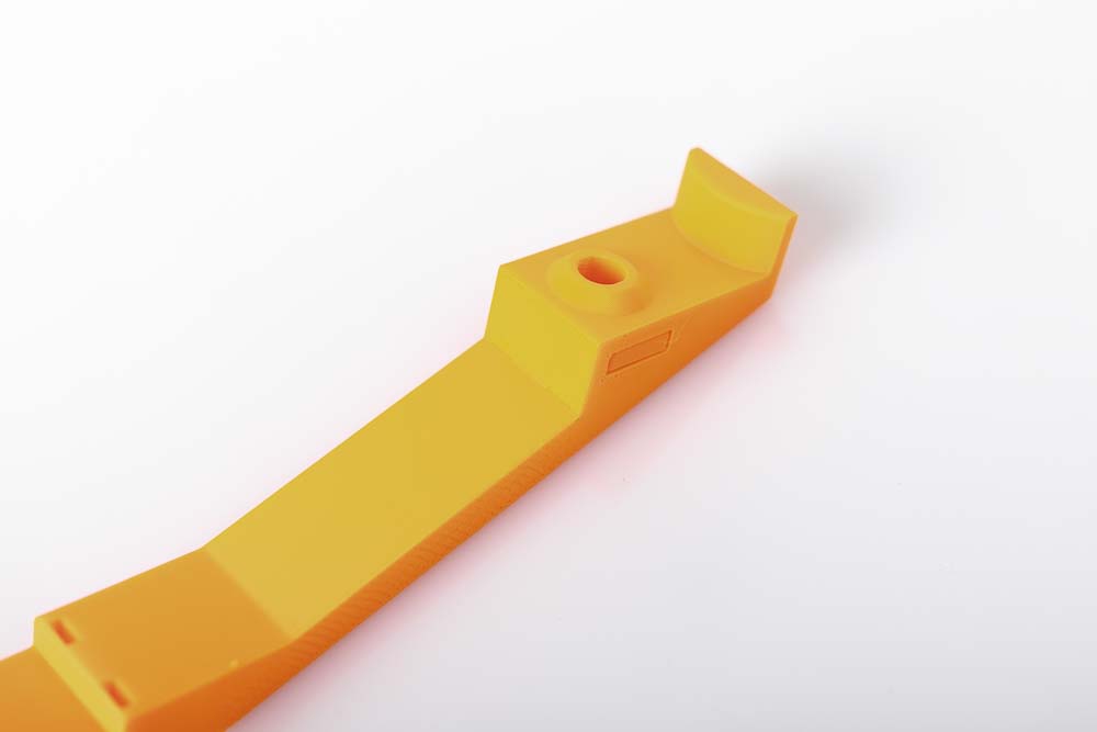
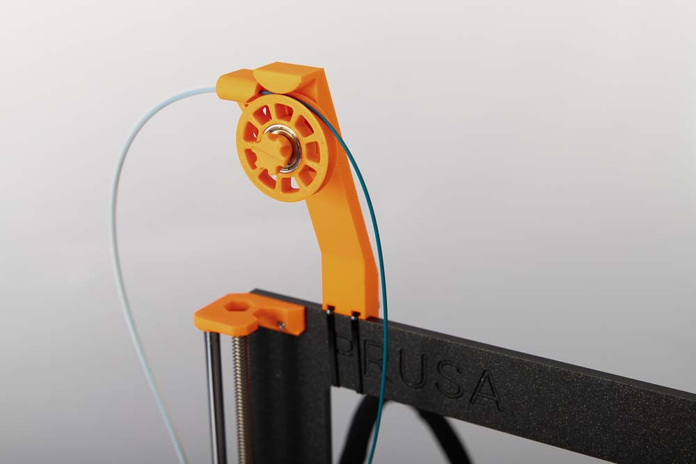
The 3D print files contain 20 different arms in various dimensions. Combinations of 5 different depths and 4 different heights allow the mounting on different 3D printers. The 3D printed models of the arms are always provided with abbreviations for height (H) and depth (D). They are always measured from the mounting edge of the arm to the highest point of the filament in the pulley.
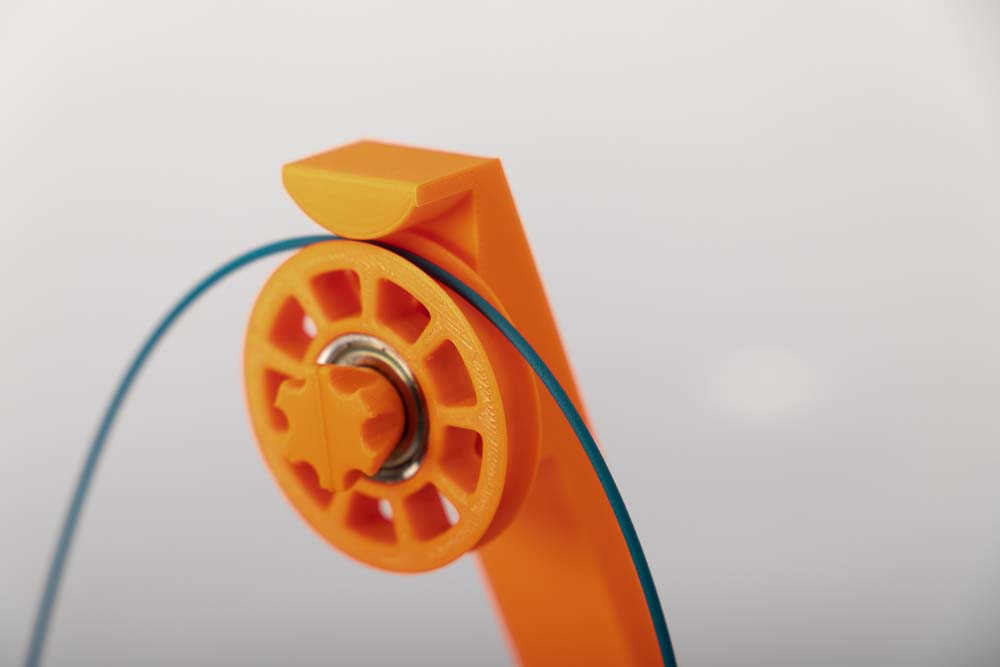
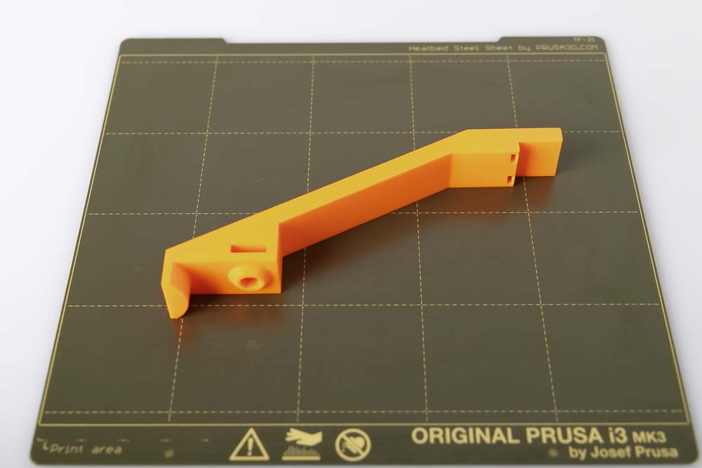
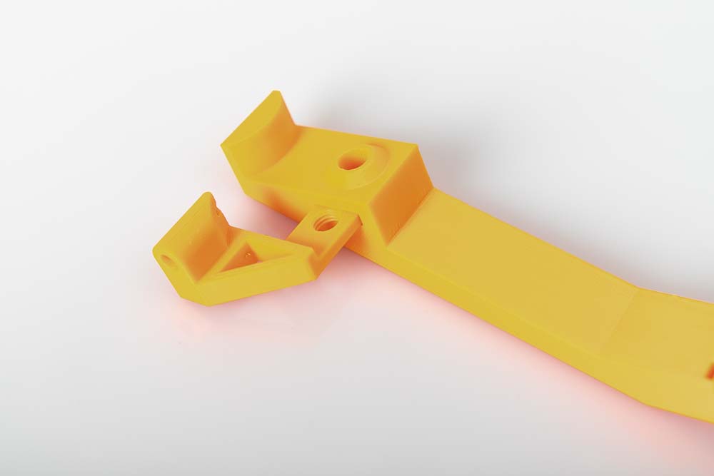
The arm shown in the cross-section below, has the designation 002600-Arm_H120_D50 and is therefore 120 mm high and 50 mm deep. Here it is mounted on a Prusa i3 MK3 model, and the recommended arm for your filament guide if you own this 3D printer.
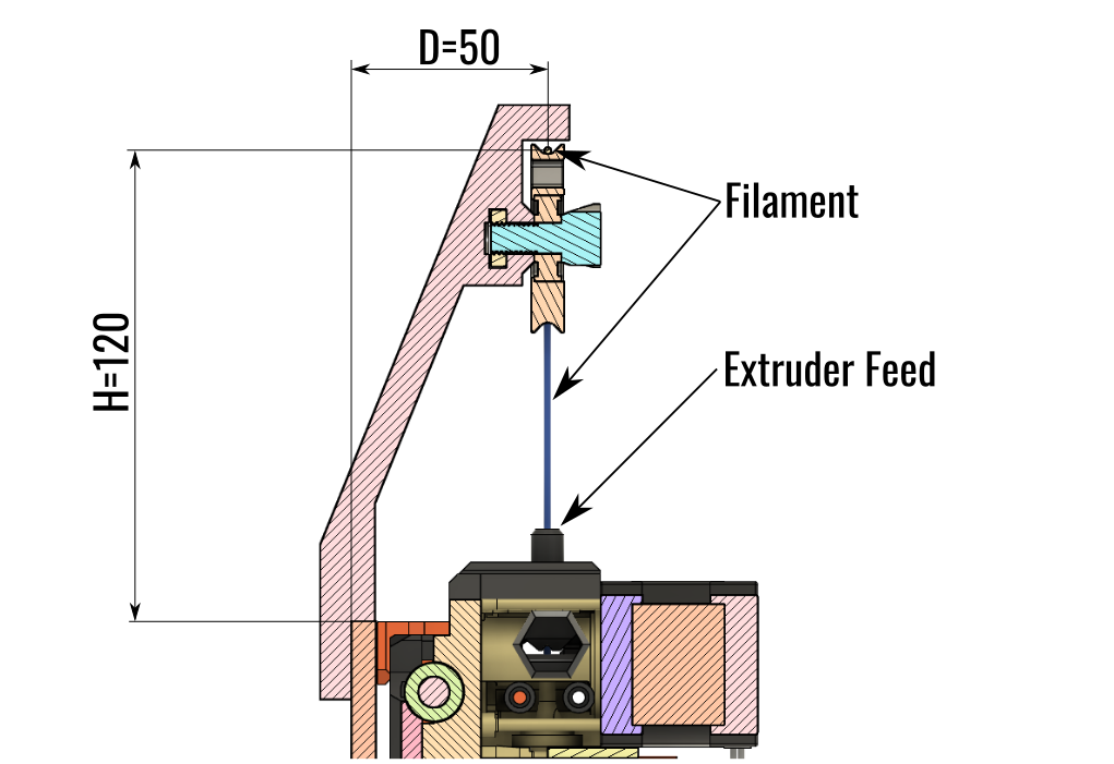
The recommended arm for the filament guide on the Prusa i3 MK3 is the one with a height of 120 mm and a depth of 50 mm. It has the designation 002600-Arm_H120_D50 in the 3D printing templates.
How do I build the optimal filament guide for my 3D printer
To determine the required depth D of the arm: measure the distance from the extruder’s filament feeder to the rear edge of the crossbar.
To determine the required height H of the arm: choose so that in the highest position of the extruder (extruder at the maximum of the Z-axis of the 3D printer) there is still enough distance between the extruder and the pulley to ensure good guidance and not too much deflection of the filament.
If you build the filament guide with pulley on a different 3D printer than the Prusa i3 MK3, then please let me (support@3d-druck-vorlagen.de) know which arm fits, I would like to add it to this instruction. If your 3D printer does need other – not included – dimensions of the arm, please just send me a request.
Various filament guide inserts for maximum flexibility
The 3D print files of the filament guide with pulley contain 9 different 3D print templates (STL files) for different designs of the filament guide. So you are able to choose between:
Variant A: simple redirection of filament or
Variant B: the filament is delivered via a PTFE tube.
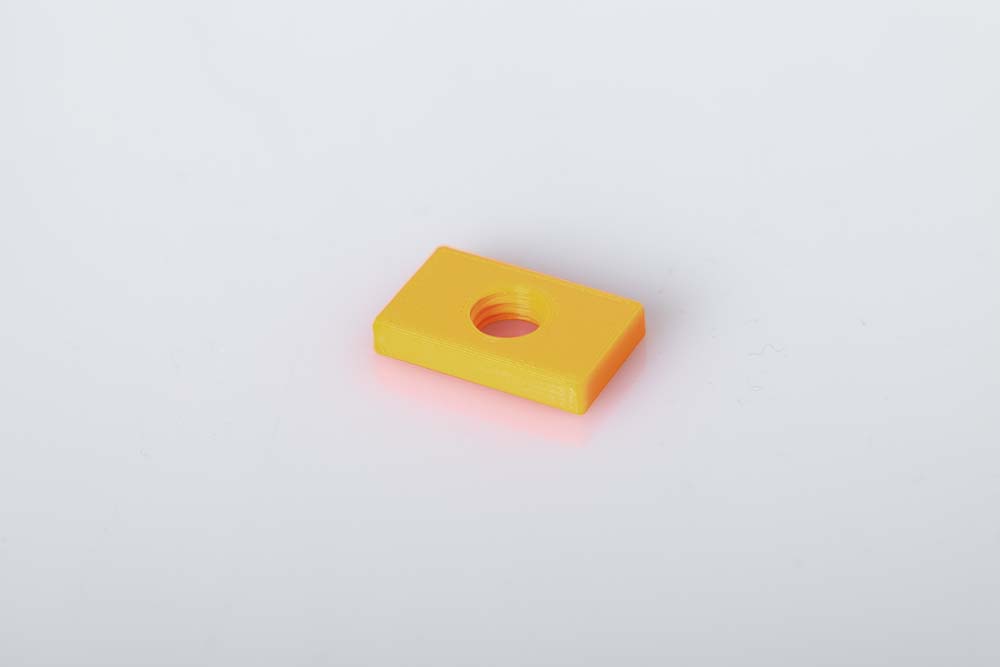
In Variant A, a simple rectangular nut is inserted into the arm, to which the pulley is attached with a screw.
With Variant B you can select from which side the filament is delivered and whether a PTFE tube with an outer diameter (OD) of 4 mm or 5 mm and whether 1.75 mm filament or 2.85 mm filament is to be used. For this, a 3D printed part called Tube_Connector_Right or Tube_Connector_Left is mounted on the arm. These options result in 8 different components that are all included in the 3D print files.
With this variant, the PTFE tube can be easily attached and detached, thanks to the conical opening on the tube connector.
Instructions: Build your own filament guide with pully
The instructions are structured as follows: first the required 3D printing parts, purchased parts and tools, followed by the assembly instructions. At the end you will find the operating manual with the safety instructions.
3D print parts
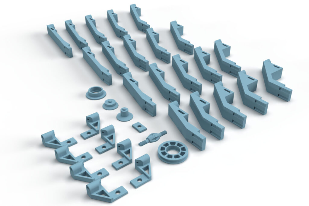
These are digital products, you get all the files you need to print the filament guide yourself in a ZIP folder. It contains the high-resolution STL files for all the required components.
- 002300_Pulley
- 002400_Screw
- 002500_Rectangular_Nut
- 002600_Arm_H##_D##
20 files of all combinations of the Heights H= 80, 100, 120, 140 mm and Depths D= 30, 40, 50, 60, 70 mm - 002700_Tube_Connector_Left_175_OD4
- 002700_Tube_Connector_Left_175_OD5
- 002700_Tube_Connector_Left_285_OD4
- 002700_Tube_Connector_Left_285_OD5
- 002800_Tube_Connector_Right_175_OD4
- 002800_Tube_Connector_Right_175_OD5
- 002800_Tube_Connector_Right_285_OD4
- 002800_Tube_Connector_Right_285_OD5
- 000400_Tool_Bearing_Press_In
- 000500_Tool_Bearing_Press_Out
- 000600_Tool_Bearing_Press_Counter
The largest 3D print part of this project (002600-Arm_H140_D70) requires a footprint (X,Y) of 170 x 85 mm and is 24 mm high (Z). Any 3D printer with a build space (X, Y, Z) of at least 170 x 170 x 25 mm is suitable for this project.
3D print settings
For the part 002600-Arm_H##_D##:
- Layer height 0.2 mm and 20% infill (rectangular)
For all other parts:
- Layer height 0.2 mm and 100% infill (rectangular)
The following settings have proven themselves for the used PETG Filament*:
- Nozzle temperature: 250°C (First layer: 240°C)
- Bed temperature: 90°C (First layer: 85°C)
- Perimeter speed: 45 mm/s (First layer: 10 mm/s)
- External and short perimeter speed: 25 mm/s (First layer: 10 mm/s)
- Infill speed: 80 mm/s (First layer: 10 mm/s)
- Top solid infill speed: 40 mm/s
Used 3D printing filament and 3D printer
For this instruction Prusament PETG Prusa Orange* Filament was printed on a Prusa i3 MK3s* 3D printer with a standard 0.4 mm nozzle.
With the selected settings, approx. 46 g PETG filament was printed for the 3D printed parts of the filament guide with pulley. At a kilo price of EUR 29.90, that is approx. EUR 1.38 material costs for one filament system.
The total printing time for all required components is approx. 4.3 hours. To calculate the total printing time, all printing times are added together, with the entire quantity of a component being printed at once.
Because of the higher stability and the low distortion , I recommend a filament made of PETG*. The parts can also be printed with ABS or ASA*, but these place higher demands on the 3D printer and operator. The widely used PLA* is not recommended because technically more demanding parts are not stable enough due to the more brittle nature of this material and the lower layer adhesion.

Be sure to print the Screw, Nut, and Tube Connector with 100% infill and a mechanically robust filament (PETG, ABS, ASA).
Bill of materials: Needed purchased parts for the filament guide
- 1 pc Ball bearing 608 (Amazon.com US)* (approx 9 USD / 20 pcs)
- 2 pcs Zip ties (Amazon.com US)* Nylon 12 in x 0.15 in (approx. 4 USD / 100 pcs)
The total cost of the purchased parts comes to around EUR 0.60 if only the costs for the parts required for one filament guide with pulley are added up.
Required tools
- Side cutters / Knips (Amazon.com US)*
- Super glue (Amazon.com US)* – optional for gluing the folded screw together
Preparation of the parts for the 3D printing project
Bill of materials: Needed purchased parts
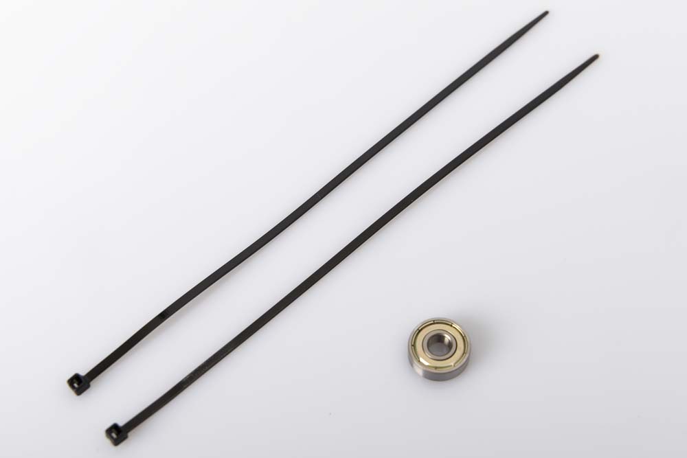
- 1 pc Ball bearing 608
- 2 pcs Zip ties
Required 3D printed parts
- 1 pc 002600_Arm_H###_D##
Layer height 0.2 mm and 20% infill (rectangular)
Select and print the appropriate arm according to the explanation in the introduction.
It is important to choose the right arm for your 3D printer! After assembly, be sure to check again whether the filament is being fed smoothly and straight to the extruder feeder.
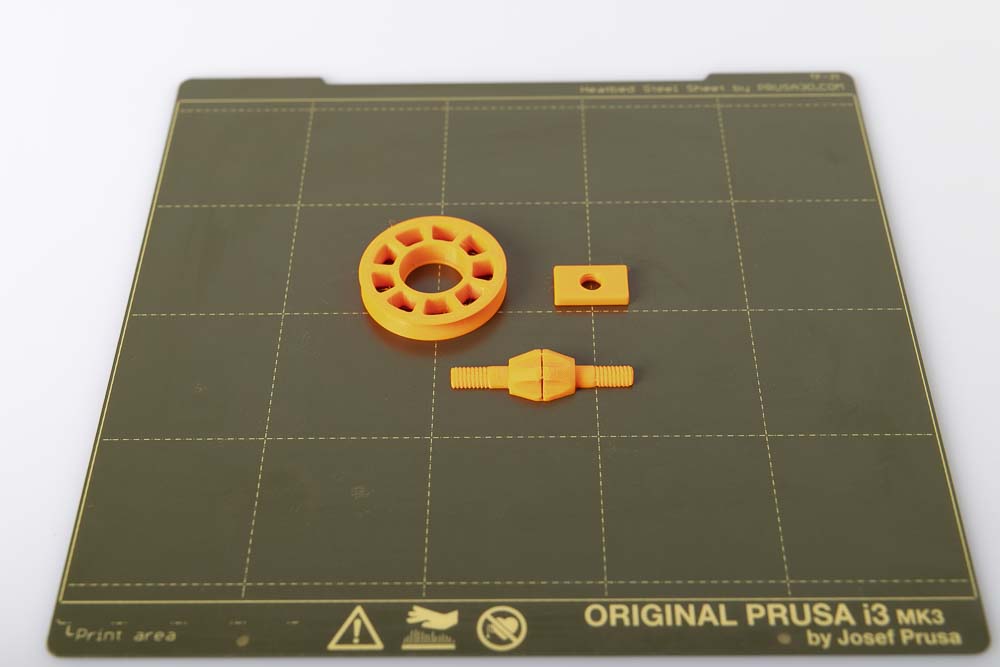
- 1 pc 002300_Pulley
- 1 pc 002400_Screw
- 1 pc 002500_Rectangular_Nut (optional)
Layer height 0.2 mm and 100% infill (rectangular)
For Variant A, print the Rectangular_Nut here.
For Variant B, select the appropriate Tube Connector from the 8 3D print models (Right/Left; PTFE tube OD4/OD5; Filament 1.75/2.85 mm).
- 1 pc 002700_Tube_Connector_Left or 002800_Tube_Connector_Right (optional)
Layer height 0.2 mm and 100% infill (rectangular)
It is important to choose the right Tube Connector for your setting! After assembly, be sure to check again whether the PTFE tube is seated properly and the filament slides smoothly through the connector to the pulley.
Optional for easier assembly and disassembly of the ball bearing in the pulley.
- 1 pc 000400_Tool_Bearing_Press_In
- 1 pc 000500_Tool_Bearing_Press_Out
- 1 pc 000600_Tool_Bearing_Press_Counter
Layer height 0.2 mm and 100% infill (rectangular)

To press the ball bearing into the filament pulley, print out the tools provided. This makes it much easier to press the bearing in and, if necessary, to press it out again.
Assembling the arm and the filament pulley
Pressing in the ball bearing
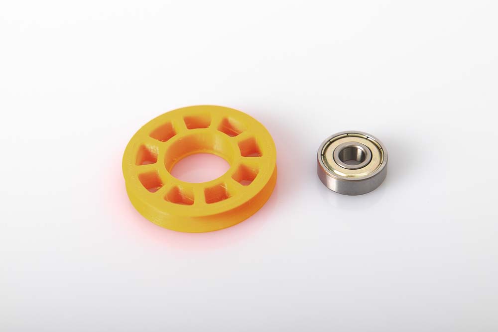
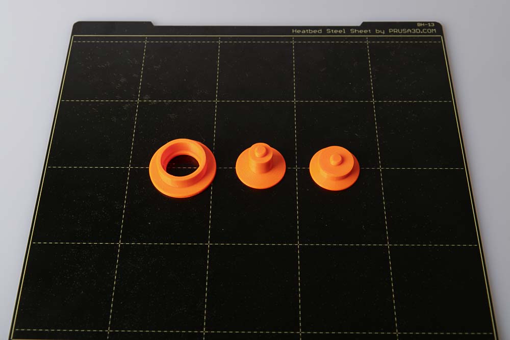
Clean the hole in the pulley intended for the ball bearing and remove any filament residue. Prepare the 608 ball bearing.
Insert the ball bearing on the side of the idler pulley that is more open.
Attach a second ball bearing as a press stamp or the 3D printed Tool_Bearing_Press_In aid and press firmly until the ball bearing is pressed completely against the stop in the pulley.
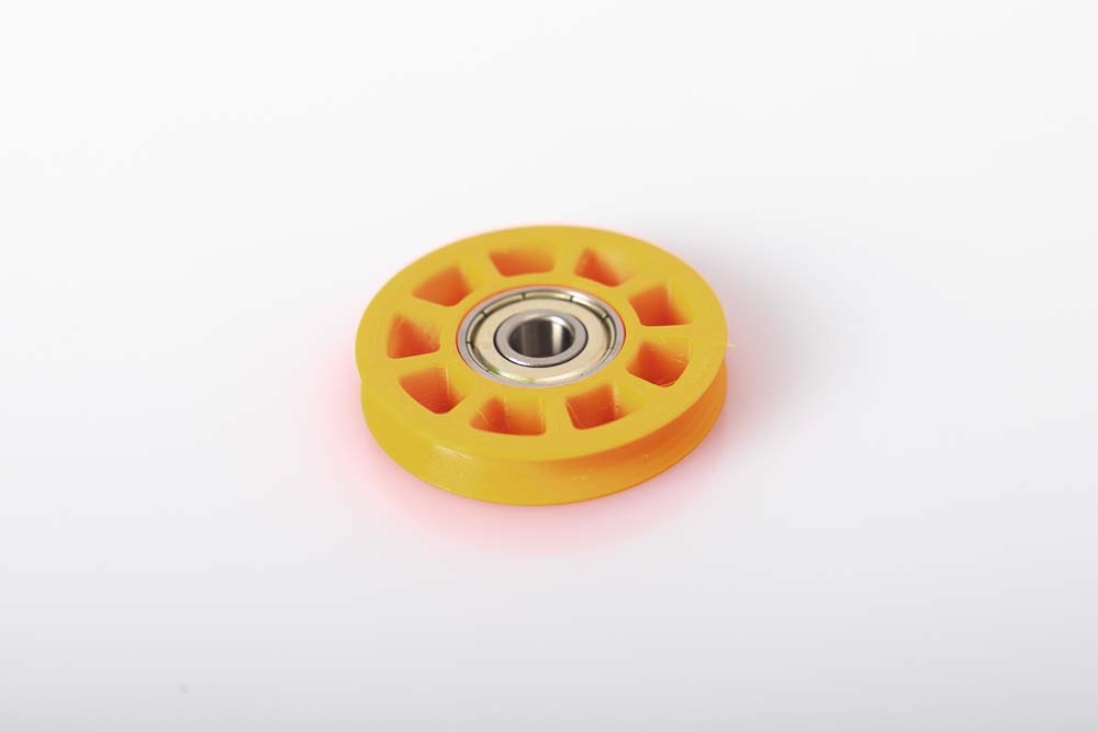
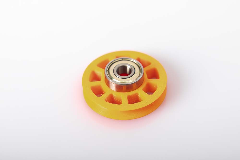
The ball bearing should be fully pressed in, parallel to the pulley and at the rear over the entire circumference against the inside stop (small step in the bore).
The ball bearing must sit securely and firmly, as well as parallel and not crooked in the filament pulley! Important so that the pulley does not block in operation!
If the ball bearing is too hard or too easy to press into the pulley, it is best to scale the pulley model up or down (in a range of 0.1 mm) in the Slicer you are using and reprint it.
If something goes wrong when pressing in, or if the ball bearing needs to be removed from the filament pulley, the Tool_Bearing_Press_Out and Tool_Bearing_Press_Counter can be used. How this works is explained in the instructions for the Filament Dry Box in the chapter Pressing a 608 ball bearing out of a roll.
Assembly of the screw
In order to save another purchased part, a 3D printed screw is used to attach the pulley. The big disadvantage of screws whose thread direction is printed in the direction of the Z-axis of a 3D printer is the low tensile strength and elongation at break in this direction. Due to the layered structure, the strength of 3D printed components in the Z-axis direction of the 3D printer are a lot worse than in the X and Y direction.
In the case of screws in particular, which are subject to high tensile loads in the longitudinal direction, it is important that the strength in this direction is high. Therefore, the screw used is halved in the middle and placed horizontally on the print bed. As a result, it benefits from the good strength in the X and Y directions, which coincide with the direction of the thread on this screw.
Due to this special printing technique for maximum strength, the screw must be folded and (optionally) glued before use.
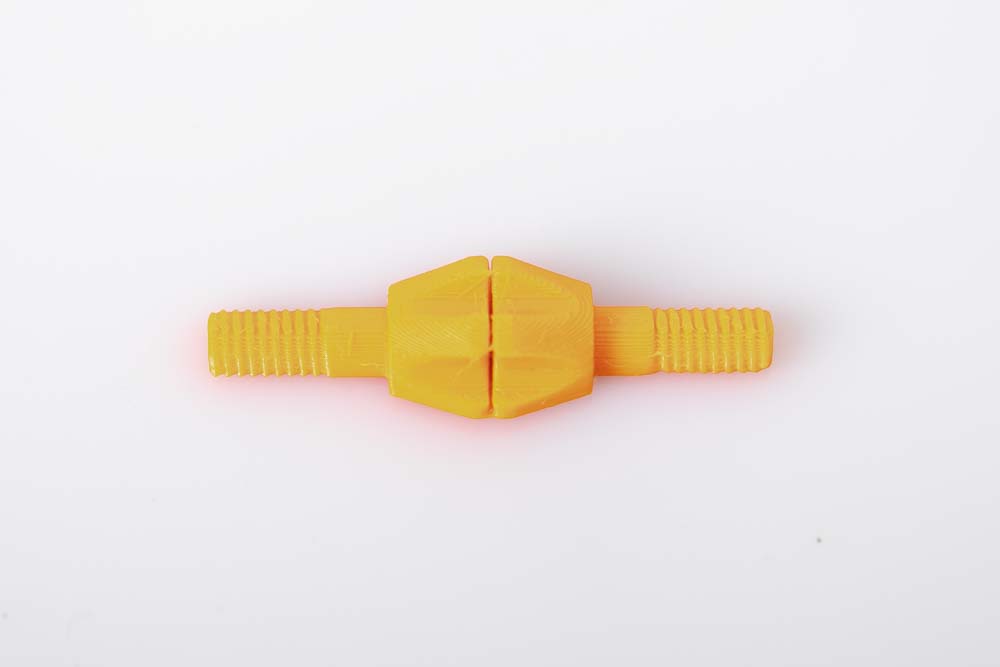
The photo shows the screw as it is removed from the print plate. The two halves of the screw are connected with a thin layer.
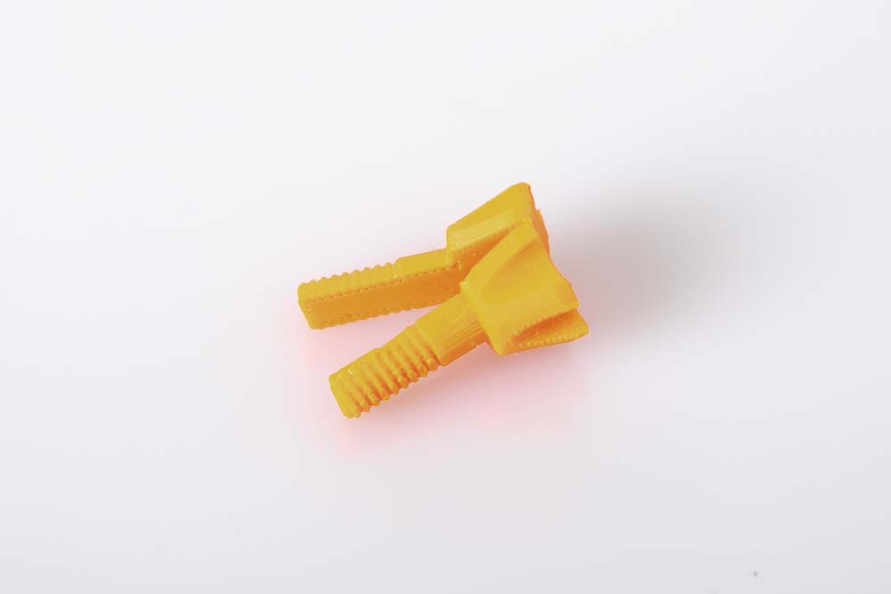
Simply fold the two halves together. The 3D printed screw can thus be screwed directly into the thread of the rectangular nut or the PTFE tube connector.
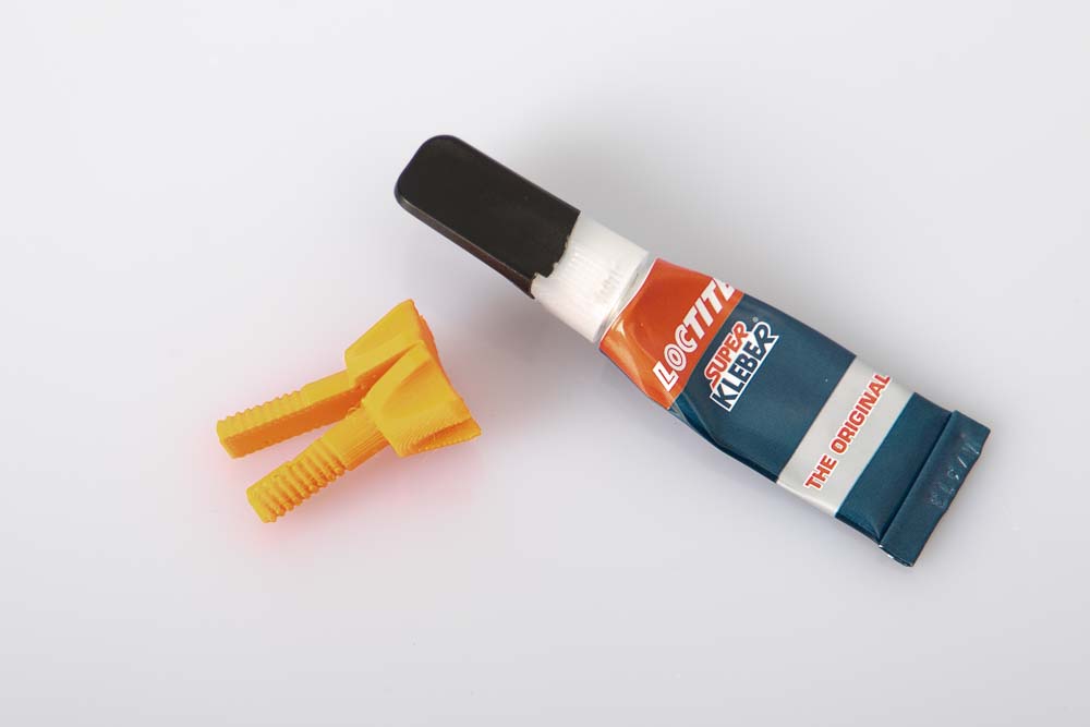
Optional – Glue the screw halves together
Lightly coat the inner surfaces with super glue and then press the two halves together.
This is only optional, simply folding the screw together and screwing it in the Nut directly is also possible.
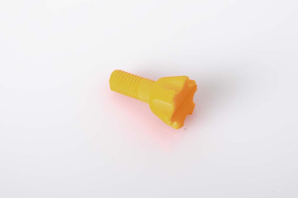
Finished 3D printed screw glued together.
Assembling of the arm and the filament pulley
The assembly of the filament guide for Variant A and then for Variant B is described below. Depending on which variant is built, skip the respective other.
Assembling of the Variant A
The following components are required to assemble Variant A:
- Arm
- Pulley with ball bearing
- Screw
- Nut
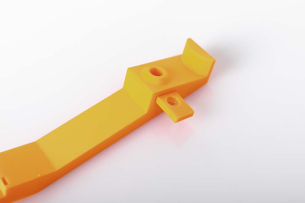
Insert the 3D printed rectangular nut into the designated slot in the arm.
Slide the nut into the arm until it sits flush with the side panels. The nut threads should be visible through the hole in the arm.
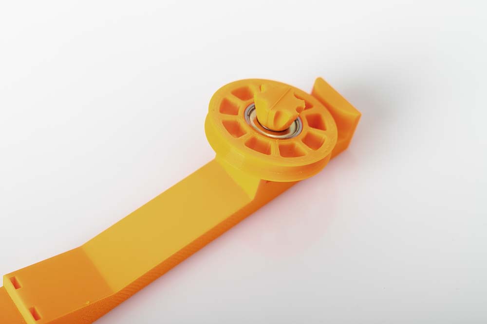
The pulley with the pressed-in ball bearing is attached to the arm with a screw.
Tighten the screw firmly, but do not use tools to avoid damaging the 3D printed threads.
Assembling of the Variant B
With this variant, a PTFE tube can be attached to and removed from the filament guide.
The following parts are required to assemble Variant B:
- Arm
- Pulley with ball bearing
- Screw
- Tube Connector
Choose the right Tube Connector for your 3D printer setup here.
Insert the rectangular part with the threaded hole of the Tube Connector into the slot provided in the arm.

Insert the 3D printed Tube Connector into the arm as far as it goes.
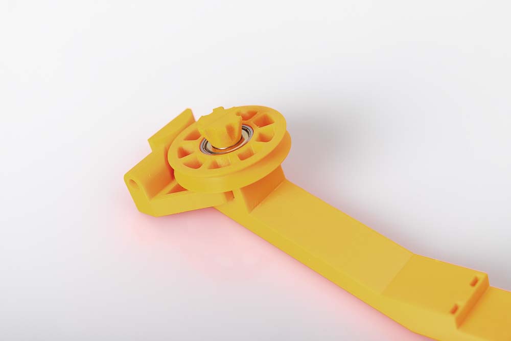
The pulley with the pressed-in ball bearing is attached to the arm with a screw.
Tighten the screw firmly, but do not use any tools to avoid damaging the 3D printed threads or the screw.
Mounting the filament guide with pulley on the 3D printer
The fully assembled filament guide is mounted on the 3D printer using two zip ties.
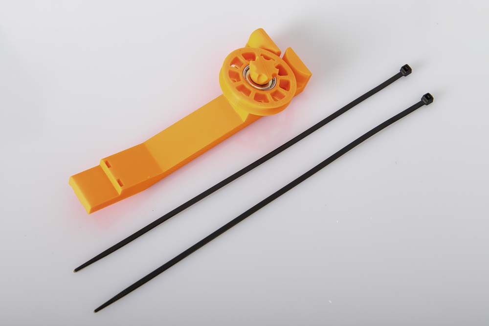
To mount the arm on the 3D printer, two zip ties and a pair of side cutters to shorten the zip ties are required.
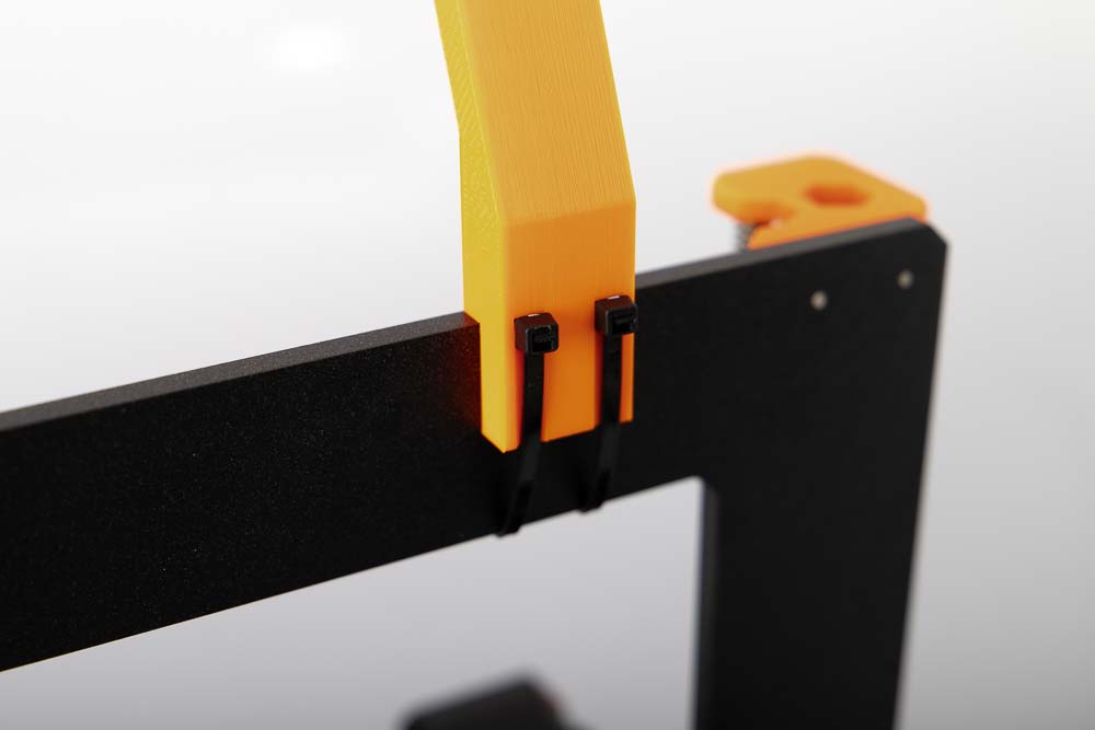
Insert the zip ties through the slots provided, the heads of the zip ties pointing upwards, as shown in the picture.
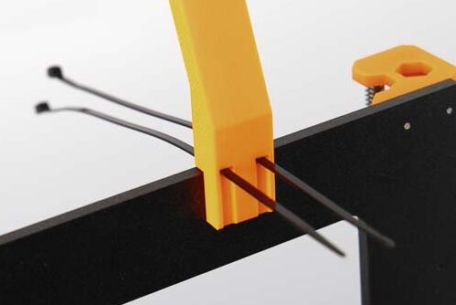
Hold the arm with the zip ties on the 3D printer’s crossbeam, positioning the edge of the arm on the upper rear edge of the crossbeam (see picture).
Place the arm on the 3D printer according to the respective filament feed. If the filament comes from the left, the arm must also be mounted on the left side of the 3D printer. If it comes from the right, then on the right side of the 3D printer.
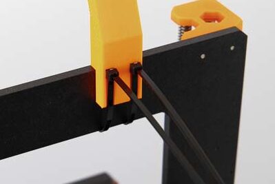
Guide the heads of the zip ties back to the slots and pull the pointed part of the zip tie through. Pull until the zip ties are sitting tight.
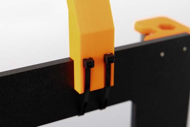
Cut off the protruding zip tie pieces with the side cutters.
Done, the filament guide system sits tight on the 3D printer. The next step is to set up the system correctly.
Setting up the filament system on the 3D printer
This step is very important to check that the system is working correctly. It should also be ensured that the filament is not bent too much during the printing process.
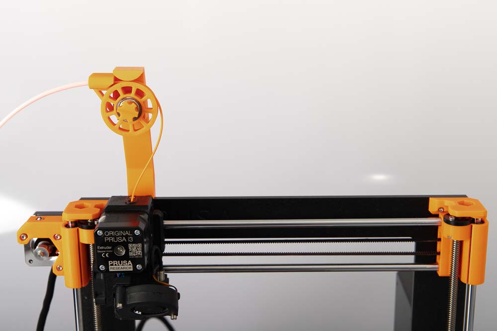
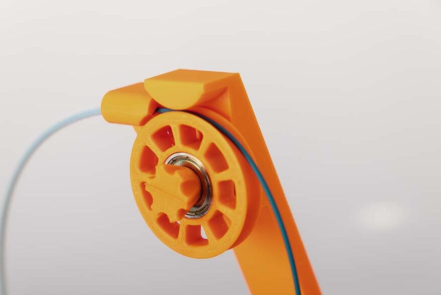
In this case (see picture), the filament is deliverd from the left side, so the arm must also be mounted on the left side of the 3D printer. Move the extruder all the way up on the Z-axis and check if the filament is bent too much or if it is alright.
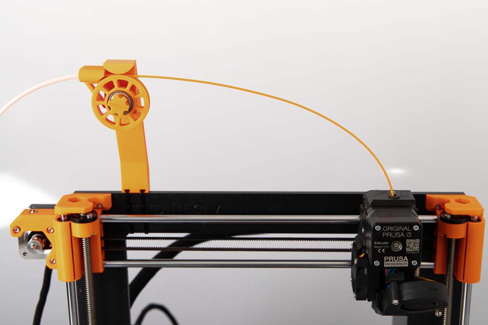
Then, as a test, move the extruder left and right along the X-axis and observe how the filament behaves.
If the filament is deliverd from the right side, mount the arm on the right side of the 3D printer.
Set up the filament guiding system according to the instructions and test whether the filament is bent too much during 3D printing and is kinked or breakes. If this is the case, change position or convert to a higher arm.
Be sure to check that the arm is securely and tight attached to the 3D printer with the zip ties.
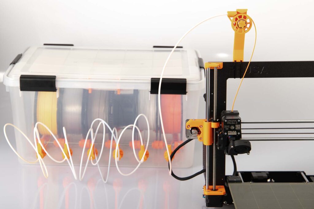
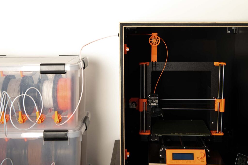
Congratulations! The system is fully assembled and ready for 3D printing. Now, for example, with Variant B, the PTFE tube of the DIY filament dry box can be attached to the Connector and the filament can be printed directly from the filament dry box.
But it is also possible to operate the 3D printer in a 3D printer enclosure and feed the filament from the outside. Variant A, which redirects the filament from the left side down to the extruder, is used here, for example. The instructions for the 3D printer enclosure can be found here:
Operating manual for the filament guide system with pulley
The filament guiding system is intended to redirect filament coming from the side of the 3D printer down to the direct drive extruder. The filament can be fed into the 3D printer either from the left or right, depending on your needs and your own assembly.
The system is only approved for 3D printers with direct drive (3D print extruder sits directly on the nozzle and moves with it). After installation, be sure to test the system and check if the filament is properly fed to the extruder. If not, correct the system if necessary, or if correction is not possible, dismantle the system.
Safety Guidelines
Safety first! Read and follow the assembly instructions and the operation manual!
Read the entire instructions and operation manual carefully and adhere to the instructions and safety guidelines. If anything is unclear, simply contact support (support@3d-druck-vorlagen.de). In the 3D print files for this project, the instructions and operation manual are also attached as PDF, keep it because you may need it later. A one-page quick guide is also included in the files with a link to this page – you will always find the latest version of the instructions and the operation manual here. If you are giving the project to someone else, then print out the instructions, operation manual and, above all, the safety instructions and pass them on with the project.
Before you start the project, also check whether the project meets the safety regulations of your respective country.
Warnings and symbols


Safety instructions for this 3D printing project
Do not leave the 3D printer unattended while printing! If the printing is interrupted or the 3D printer makes unusual noises, switch off the 3D printer immediately, check the filament box and the filament feed!
Also read through, follow and keep the operation manuals and safety instructions for the purchased parts!
Attention for all purchased parts: Before assembling, check whether they meet the safety regulations in your country and whether the dimensions, function and stability are fine. Repeat this safety check at regular intervals and before using the project. If a part is damaged or no longer suitable, then discontinue use of the project until the defective part has been replaced.
Attention for all self-printed parts: Due to incorrectly set printing parameters, poor material, incorrect material selection, poor layer adhesion and other reasons, these can sometimes not meet the requirements needed on them and thus break, fail or their functionality cannot be guaranteed. In the event of a break, the parts can splinter and the fracture surface leave sharp edges. Take particular care when replacing these parts, there is a risk of cuts! Check 3D printed parts for cracks, stability and functionality at regular intervals and before using the project. If a part is damaged or unsuitable, do not continue to use the project until the broken part has been replaced with a new, improved part.
When printing parts, sharp edges can occur (usually on the first layer), there is a risk of cuts! These edges have to be ground down in order to deburr them.
Loading the filament
Variant A: thread the filament through the notch in the pulley and pull it down on the other side. Check if the filament lies well in the notch of the pulley.
Variant B: pull a longer piece of filament out of the PTFE tube and insert it through the hole provided in the tube connector. Pull the filament down over the pulley and check if the filament sits well in the notch of the pulley. Then insert the PTFE tube into the hole provided in the tube connector. If the filament does not fit through the connector or if the PTFE tube does not sit well in the connector, then check the tube connector and replace it if necessary.
For both Variants, check before and during 3D printing that the filament or the PTFE tube does not get into the mechanics of the 3D printer.
For Variant B: Check whether the tube connector is installed with the correct filament diameter (1.75 mm or 2.85 mm) and the correct outer diameter (4 mm or 5 mm) for your own setting.
Before operation
Before using it for the first time, make sure that the system is suitable for your own 3D printer and that it works properly.
Always do a short safety check before operation and carry out subsequent checks.
Security check before printing
- Before operating the 3D printer and the filament guide system with pulley, it is essential to check whether the arm is firmly attached to the 3D printer and the pulley can be rotated easily. Do not operate if this is not the case.
- Check whether the filament runs properly over the pulley and is not jammed or runs behind the pulley.
In operation
From time to time during the print, visually check whether the filament is properly redirected and feeded into the 3D print extruder.
Never reach into the pulley, there is a risk of injury from the rotating parts!
Do not leave the 3D printer unattended while printing! If the printing is interrupted or the 3D printer makes unusual noises, switch off the 3D printer immediately, check the filament box and the filament feed!
Check if the arm moves along the 3D printer’s crossbeam, if it does, stop printing and check the mounting and tighten the zip ties if necessary.
Disclaimer
The instructions and the associated files are an inspiration of Ingenieurbüro Dr. Janko GmbH to build this project yourself. Since Ingenieurbüro Dr. Janko GmbH has no way of checking and influencing the required quality of the printed components and purchased parts as well as the quality of the assembly and the correct functioning of the project or if any inadmissible changes and modifications to the project has been made, Ingenieurbüro Dr. Janko GmbH accepts no liability for functionality, stability or the damage incurred by the project.
Wow, Great tutorial. Love the instructions, keep it up.
Hi Felix!
Thank you very much!
Happy printing
Marian